Tree seedling lifter

A seedling lifter and tree technology, applied to the upper structure and application of motor vehicles and trucks, can solve the problems of easy dumping of operators, time-consuming, labor-intensive, dangerous, etc., and achieve the effect of saving manpower

Inactive Publication Date: 2020-12-25
李鸿
View PDF0 Cites 0 Cited by
  • Summary
  • Abstract
  • Description
  • Claims
  • Application Information

AI Technical Summary

Benefits of technology

This patented technology allows for an automated system called Hydrator® (a type of machine) used during tree harvest operations. It uses a special device made by mounting a hydrocylindrical piston onto a stationery surface or backbone structure attached to a moving part like a vehicle chassis. By placing this device along the length of the plant's stem, water pressure causes movement within the chamber where the nutrients flow downward towards the rootstock area causing them to break off roots without damaging any nearby plants. Additionally, there may also have some devices mounted outside the crop field near the ground level to help control soil-borne diseases such as insect infestation caused by fungi. Overall, these technical features improve efficiency and safety during forestry production while minimizing human labor costs associated with manual excavations.

Problems solved by technology

The technical problem addressed in this patented text relates how to efficiently transfer or lift small branches from one location into another without having to manually dig them up with heavy tools like jacks for lifting large numbers of young plants that may have potential safety hazards during transportation.

Method used


Image

  • Tree seedling lifter
  • Tree seedling lifter
  • Tree seedling lifter

Examples


Embodiment Construction

[0023] The following will clearly and completely describe the technical solutions in the embodiments of the present invention with reference to the accompanying drawings in the embodiments of the present invention. Obviously, the described embodiments are only some, not all, embodiments of the present invention. Based on the embodiments of the present invention, all other embodiments obtained by persons of ordinary skill in the art without making creative efforts belong to the protection scope of the present invention.

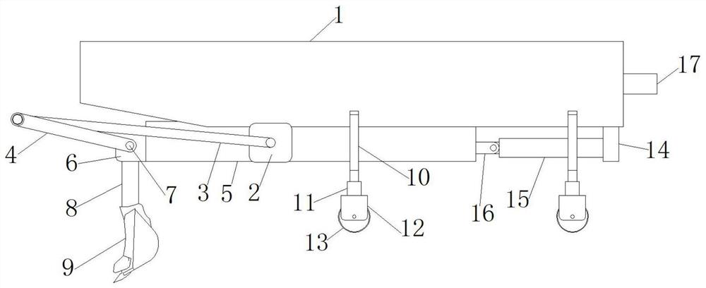
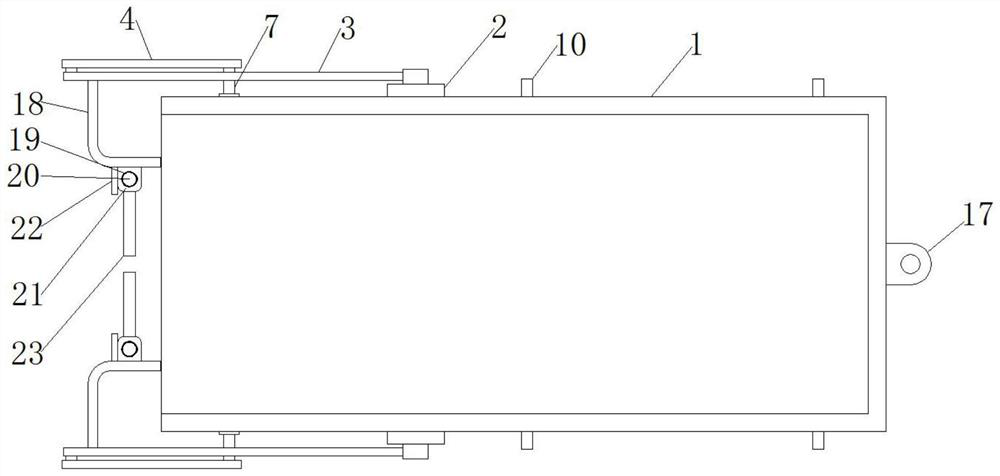
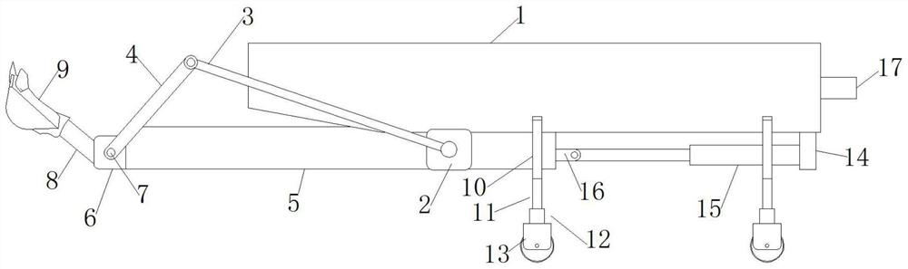
[0024] see Figure 1-5 , the present invention provides a technical solution: a tree seedling lifter, comprising a compartment 1, a fixed plate 2 is fixedly installed outside the bottom of the compartment 1, and a main rod 3 is movably installed outside the central position of the fixed plate 2, so A secondary rod 4 is movably installed on the outside of one end of the main rod 3 away from the fixed plate 2, a slide plate 5 is slidably installed on the inside of


PUM


Abstract

The invention discloses a tree seedling lifter. The tree seedling lifter comprises a carriage; a sliding plate is slidably mounted at the inner side of the bottom of the carriage; a fixing frame is fixedly mounted at the end, close to an auxiliary rod, of the sliding plate; the auxiliary rod is movably mounted at the outer side of the end, away from a fixing plate, of a main rod; supporting rods are fixedly mounted at the outer side of the carriage; fixing bases are fixedly installed at the bottoms of electric push rods; wheels are movably installed at the inner sides of the fixing bases; a fixing block is fixedly installed at the bottom of the end, away from the fixing frame, of the carriage; a hydraulic cylinder is fixedly installed at the side, close to the fixing frame, of the fixing block; a connecting frame is fixedly installed at the end, close to the hydraulic cylinder, of the sliding plate; the connecting frame is fixedly connected with the hydraulic cylinder; and a bent rod is fixedly mounted at the inner side of the end, away from the carriage, of the main rod, and the bent rod is bent by 90 degrees. According to the tree seedling lifter, through the extension and retraction of operation of the hydraulic cylinder, the main rod and the auxiliary rod are further driven to rotate through the sliding plate, so that a digging bucket is driven to rotate, and seedling lifting and truck loading of trees can be achieved.

Description


Claims


Application Information

Patent Timeline
Owner 李鸿
Why Eureka
Try Eureka