Feeding mechanism
A material feeding and feeding technology, which is applied in the direction of metal processing machinery parts, metal processing, measuring/indicating equipment, etc., can solve the problem of slow feeding efficiency, achieve the effect of improving feeding efficiency and avoiding object jamming
- Summary
- Abstract
- Description
- Claims
- Application Information
AI Technical Summary
Benefits of technology
Problems solved by technology
Method used
Image

Examples
Embodiment 1
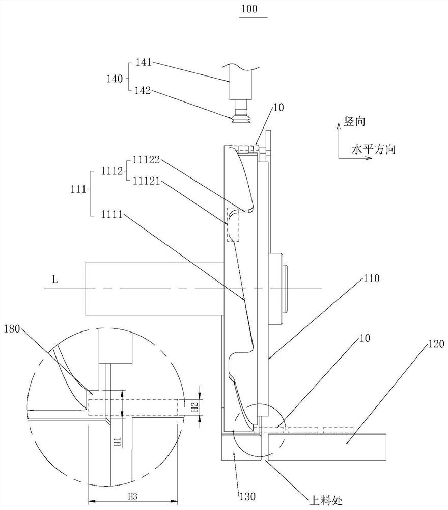
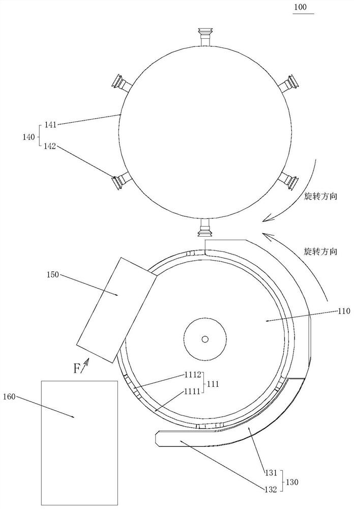
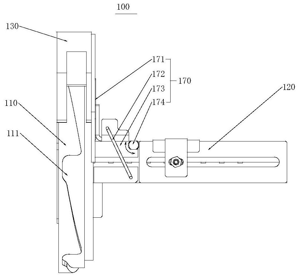
[0041] see Figures 1 to 3 , figure 1 The structural schematic diagram of the feeding mechanism in Embodiment 1 of the present application, figure 2 yes figure 1 right view of the image 3 yes figure 1 top view.
[0042] Such as Figures 1 to 3 As shown, the present application provides a feeding mechanism 100 , and the feeding mechanism 100 includes a feeding assembly 120 , a turntable 110 , a rib 130 and a retrieving assembly 140 .
[0043] The feeding assembly 120 is used to convey the object 10 , specifically, the feeding assembly 120 conveys the object 10 along the horizontal direction. The feeding assembly 120 is a conventional conveyor, such as a belt conveyor and an air channel conveyor, which is not limited in this application.
[0044] The turntable 110 can rotate around its own axis, and one side of the turntable 110 ( figure 1 Middle right side) towards the feeding assembly 120. The outer periphery of the turntable 110 is provided with a plurality of grooves
Embodiment 2
[0077] see Figure 5 and Figure 6 , Figure 5 It is a schematic structural view of the feeding mechanism in Example 2 of the present application, Figure 6 yes Figure 5 A-A sectional view in .
[0078] like Figure 5 and Figure 6 As shown, the present application provides a feeding mechanism 200 including a feeding assembly 220 and a turntable 210 .
[0079] The feeding component 220 conveys the object 10 in the horizontal direction. The feeding assembly 220 is a conventional conveyor, such as a belt conveyor and an air channel conveyor, which is not limited in this application.
[0080]The turntable 210 can rotate around its own axis, and its axis is vertically arranged (the turntable 210 is placed horizontally). The outer circumference of the turntable 210 is provided with a plurality of grooves 211 at intervals, and each groove 211 is recessed downward from the top surface 212 of the turntable 210 Formed, and an opening is formed on the outer peripheral side wall of
PUM
 Abstract
Description
Claims
Application Information
 - R&D Engineer
- R&D Manager
- IP Professional
- Industry Leading Data Capabilities
- Powerful AI technology
- Patent DNA Extraction
Browse by: Latest US Patents, China's latest patents, Technical Efficacy Thesaurus, Application Domain, Technology Topic.
© 2024 PatSnap. All rights reserved.Legal|Privacy policy|Modern Slavery Act Transparency Statement|Sitemap