Multi-stage axial-flow compressor of gas turbine

A gas turbine, axial flow technology, applied in axial flow pumps, machines/engines, liquid fuel engines, etc., can solve the problems of device surge, short engine length, insufficient handling of inflowing gas volume, etc., and solve the problem of being vulnerable to damage , Enhance the effect of separation

Pending Publication Date: 2021-01-26
徐煜
View PDF4 Cites 0 Cited by
  • Summary
  • Abstract
  • Description
  • Claims
  • Application Information

AI Technical Summary

Problems solved by technology

[0003] At present, there are many types of axial flow compressors on the market, but when the existing devices add power and pressurize the inflowing gas, dust and larger particles in the external environment are often sucked into the device and the blades of the turbine. These dusts will greatly affect the normal operation of the device. At the same time, the air intake of the existing device is small. Due to the short length o

Method used


Image

  • Multi-stage axial-flow compressor of gas turbine
  • Multi-stage axial-flow compressor of gas turbine
  • Multi-stage axial-flow compressor of gas turbine

Examples


Example Embodiment

[0023]The technical solutions in the embodiments of the present invention will be clearly and completely described below in conjunction with the accompanying drawings in the embodiments of the present invention. Obviously, the described embodiments are only a part of the embodiments of the present invention, rather than all the embodiments.

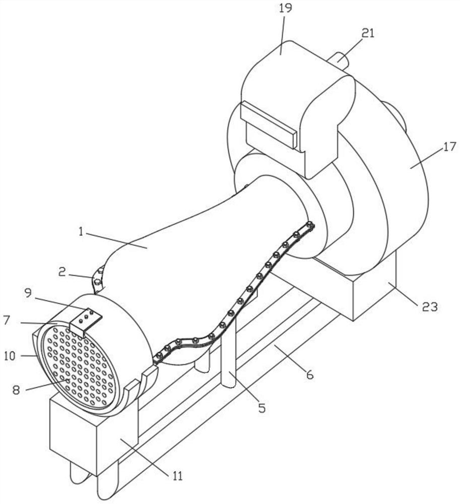
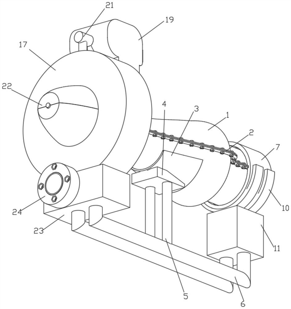
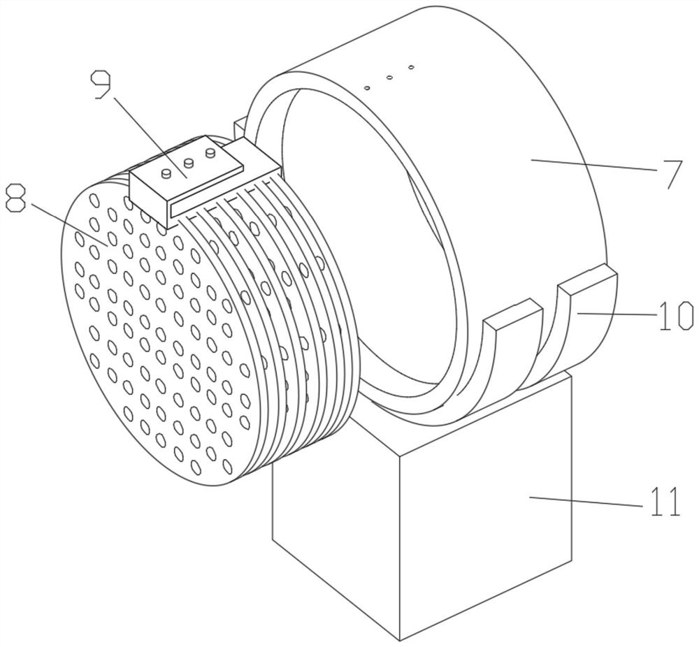
[0024]SeeFigure 1 to Figure 5, The present invention provides a technical solution: a multi-stage axial compressor for a gas turbine, comprising a casing 1, symmetrically distributed positioning pieces 2 are fixedly connected to both sides of the outer casing 1, and the overall shape of the casing 1 is a curved arc The outside of the positioning piece 2 is provided with evenly distributed and threaded holes. The threaded holes on the outside of the positioning piece 2 are movably connected with evenly distributed fixing nuts. The shape of the positioning piece 2 is adapted to the curved surfaces on both sides of the outer shell 1. , By fixing and con


PUM


Abstract

The invention discloses a multi-stage axial-flow compressor of a gas turbine, and relates to the technical field of compressors, in particular to a multi-stage axial-flow compressor of a gas turbine.The multi-stage axial-flow compressor comprises a shell, wherein positioning pieces which are symmetrically distributed are fixedly connected to the two sides of the outer part of the shell, and fixing rings are fixedly connected to the bottoms of the positioning pieces; and the bottoms of the fixing rings are fixedly connected with fixing clamping blocks. According to the multi-stage axial-flow compressor of the gas turbine, a sleeve is fixedly connected to the left end of the shell, symmetrically-distributed filter screen plates are movably connected to the interior of the sleeve, and a buckle is fixedly connected to the tops of the filter screen plates; and meanwhile, the buckle is stably buckled to the exterior of the sleeve, fixing nuts are movably connected to the top of the buckle,and the overall stability between the filter screen plates and the sleeve is controlled through the fixing nuts, so that it can be guaranteed that the device can filter dust in outside air, and thus the problem that an existing device is prone to being blocked by the dust is solved.

Description


Claims


Application Information

Patent Timeline
Owner 徐煜
Why Eureka
Try Eureka