Compact optical structure for light field display

An optical structure and compact technology, applied in optics, optical components, instruments, etc., can solve the problem of large focal length of projection lens and achieve the effect of compact structure

Active Publication Date: 2021-03-02
SUN YAT SEN UNIV
View PDF7 Cites 0 Cited by
  • Summary
  • Abstract
  • Description
  • Claims
  • Application Information

AI Technical Summary

Benefits of technology

This patented technology allows for creating an eyewear that displays images without requiring special glasses or equipment like binoculars. Instead it utilizes multiple layers made up by specific materials called LC (Luminescent Conjugate) molecules which are excited when exposed to certain wavelengths of electromagnetic radiation. These excitation levels change their properties depending upon how much energy they emit them at each time. By combining these changes into one layer, this material becomes transparent overlappingly across two adjacent pixels. When viewed under both eyes simultaneously, we see clearly colored patterns appearing between those colors due to interference caused by reflections off objects behind us' faces.

Problems solved by technology

This patented describes an improved method for displaying images without causing any confusion between what they are looking at and how it looks like. Instead of relying solely upon their own brain responses or other sensory input, this new approach uses multiple cameras placed close together around one another instead of just showing them sideways across the screen. By doing this, users don’t have to pay attention but still get clear pictures even if there may seem too much distraction.

Method used


Image

  • Compact optical structure for light field display
  • Compact optical structure for light field display
  • Compact optical structure for light field display

Examples


Embodiment Construction

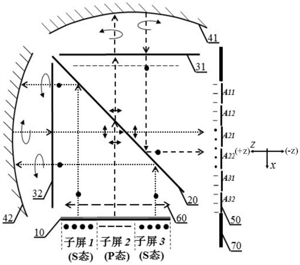
[0049] The optical structure of the present invention selects display screens with different polarization states of outgoing light in different regions, uses polarized beam splitters as light beam splitting and light fusion devices, and combines reflective phase modulation devices and wave plates to easily realize short The characteristics of the focal length lens and the reentry of the optical path, combined with the monocular multi-view light field technology of the previous patent PCT15 / 481,467, build a compact optical structure for light field display.

[0050] The compact optical structure for light field display is as figure 1 , the optical structure includes an imaging component, a small-pitch aperture array 50, a control unit 80, and a diaphragm 70, wherein the imaging component includes a polarizing beam splitter 20 described below, a display screen 10, two wave plates 31, 32, two reflectors Modulators 41,42. The system uses the polarizing beam splitter 20 as a beam s


PUM


Abstract

The invention discloses a compact optical structure for light field display. The compact optical structure comprises an imaging assembly comprising: a polarizing beam splitter that completely reflectsan incident beam in an S-state polarizing state and completely transmits an incident beam in a P-state polarizing state, a display screen composed of M sub-screens, and enabling light information emitted by all the sub-screens to enter the polarizing beam splitter respectively, two wave plates used for changing the polarization state of the incident light beam, and two reflection modulation devices used for carrying out phase modulation on the light. The compact optical structure further comprises a small-spacing aperture array, a control unit and a diaphragm. According to the compact opticalstructure for light field display, a compact optical structure capable of realizing monocular multi-view presentation is designed by virtue of the regulation and control of the polarization spectroscope and the wave plate on the polarization state, so that the three-dimensional visual comfort is improved by virtue of three-dimensional display capable of being naturally focused. The compact optical structure can be used as an eyepiece of a head-mounted VR/AR alone.

Description


Claims


Application Information

Patent Timeline
Owner SUN YAT SEN UNIV
Why Eureka
Try Eureka