SIP feeding mechanism operation method and structure

An operation method and a material tray technology, which are applied in the field of mechanical processing, can solve problems such as low efficiency, lack of front-end scanning code detection, assembly and combination functions, etc., and achieve the effect of saving space and saving process steps

Pending Publication Date: 2021-03-16
深圳双十科技股份有限公司
View PDF7 Cites 0 Cited by
  • Summary
  • Abstract
  • Description
  • Claims
  • Application Information

AI Technical Summary

Problems solved by technology

Therefore, the main purpose of the present invention is to provide an operation method and structure of a SIP feeding mechanism, aiming at solving the problem that the front end of the lens module processing proc

Method used


Image

  • SIP feeding mechanism operation method and structure
  • SIP feeding mechanism operation method and structure
  • SIP feeding mechanism operation method and structure

Examples


Embodiment 1

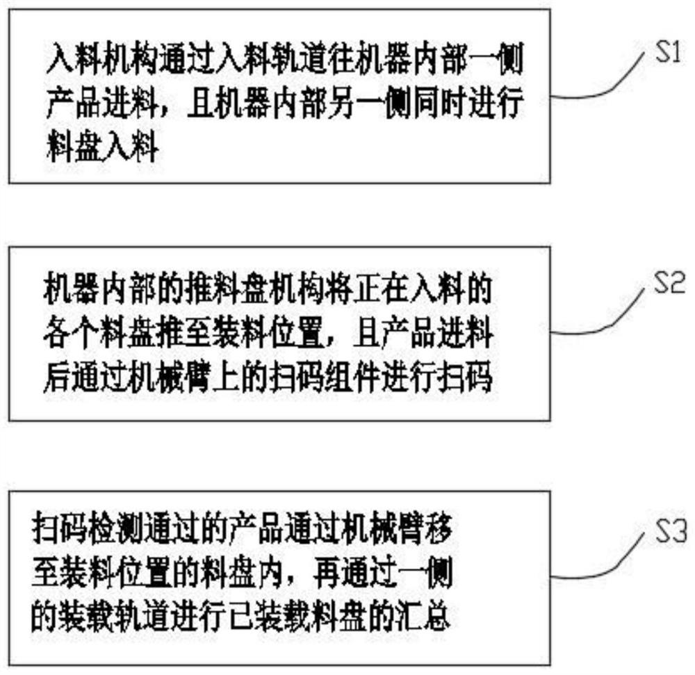
[0037] refer to Figure 1 to Figure 5 , a method for operating a SIP feeding mechanism, comprising the following operating steps:

[0038] The feeding mechanism feeds the product on one side of the machine through the feeding track, and the other side of the machine simultaneously feeds the material into the tray;

[0039] The pushing tray mechanism inside the machine pushes each feeding tray to the loading position, and after the product is fed, it scans the code through the code scanning component 221 on the mechanical arm;

[0040] The products that pass the scanning code inspection are moved to the tray at the loading position by the robotic arm, and then the loaded trays are collected through the loading track on one side.

[0041] When the detection fails, the NG product is loaded into the NG tray by the mechanical arm and moved to the NG loading track.

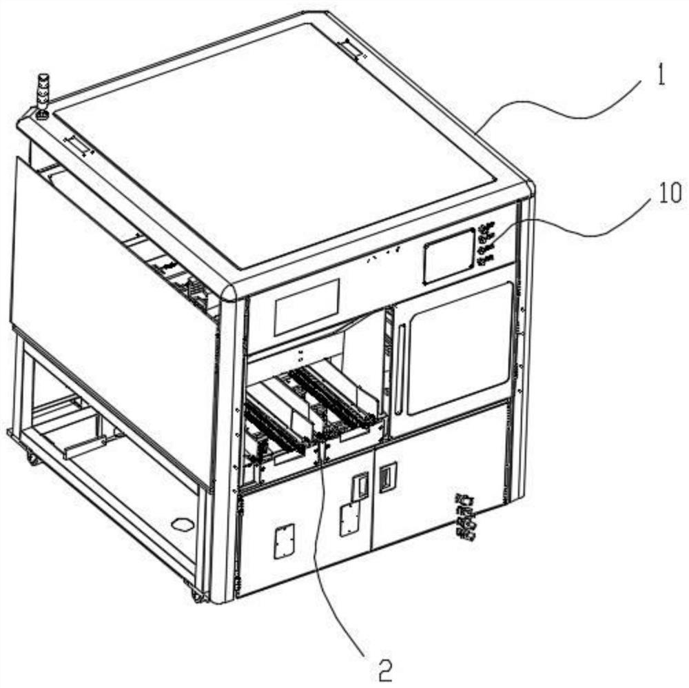
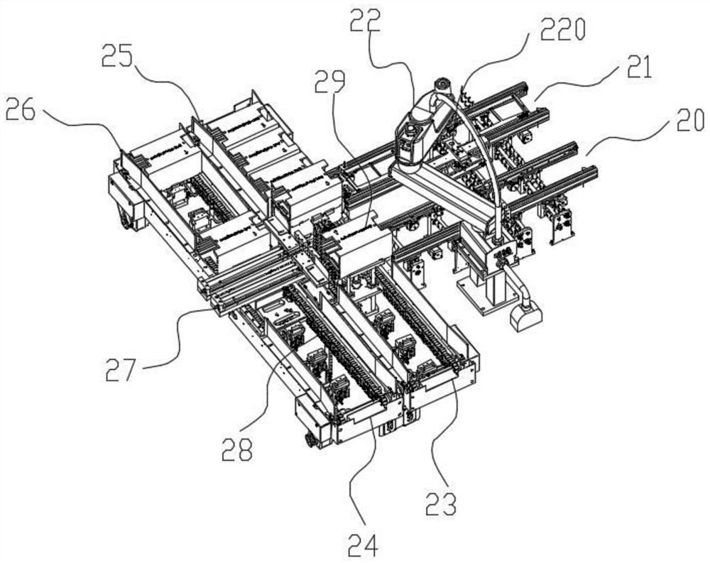
[0042] refer to Figure 1 to Figure 5 , the SIP feeding mechanism structure includes an external casing 1 and a mater


PUM


Abstract

The invention discloses an SIP feeding mechanism operation method and structure. The SIP feeding mechanism operation method comprises the steps that a feeding mechanism feeds products to one side of the interior of a machine through a feeding rail, and tray feeding is conducted on the other side of the interior of the machine at the same time; S2, a material pushing disc mechanism in the machine pushes each material disc which is being fed to a loading position, and after the products are fed, code scanning is carried out through a code scanning assembly on a mechanical arm; and S3, the products passing the code scanning detection are moved to trays at charging positions through the mechanical arm, and then the loaded trays are gathered through a loading rail on one side. The problems thatin the prior art, the front end of a lens module machining procedure can only conduct independent feeding and arranging of the trays or products, efficiency is low, and the front end code scanning, detecting, assembling and combining functions are not achieved are solved.

Description


Claims


Application Information

Patent Timeline
Owner 深圳双十科技股份有限公司
Why Eureka
Try Eureka