Electric power intelligent switch cabinet with heat dissipation function

A smart switch and power technology, applied in the field of switch cabinets, to achieve the effects of reducing dust generation, temperature guidance and control, and stable and powerful functions

Active Publication Date: 2021-03-19
江苏乐仕电气科技有限公司
View PDF5 Cites 3 Cited by
  • Summary
  • Abstract
  • Description
  • Claims
  • Application Information

AI Technical Summary

Benefits of technology

This technology allows for better cooling performance without causing excessive noise or vibrations that could be annoying during operation. It also prevents damage caused due to overheating when there are many hot spots on an insulated panel system. Additionally, it can adjust the amount of power needed based upon factors like humidity levels and ambient temperatures. Overall, this innovation improves thermal efficiency while reducing environmental impacts associated with current systems used for refrigerators.

Problems solved by technology

This patented technical solution described by the present patents improves how an electrical equipment (EI) works properly when there are no issues or concerns about its safe operation due to overheat conditions caused during use. By allowing automatic regulation of heat transfer from inside the EMI housing into outside air through various mechanisms like fans, water pipes, etc., these improvements help prevent damage to components such as circuit boards and other electronic devices within the device's interior space.

Method used


Image

  • Electric power intelligent switch cabinet with heat dissipation function
  • Electric power intelligent switch cabinet with heat dissipation function
  • Electric power intelligent switch cabinet with heat dissipation function

Examples


Embodiment Construction

[0018] The following will clearly and completely describe the technical solutions in the embodiments of the present invention with reference to the accompanying drawings in the embodiments of the present invention. Obviously, the described embodiments are only some, not all, embodiments of the present invention. Based on the technical solutions in the present invention, all other embodiments obtained by persons of ordinary skill in the art without making creative efforts belong to the protection scope of the present invention.

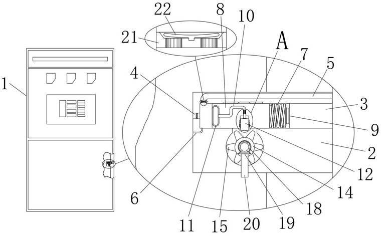
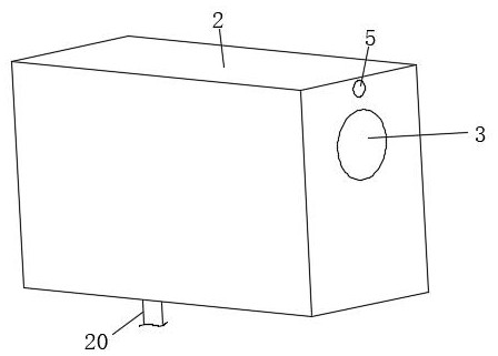
[0019] see Figure 1 to Figure 3 , the present invention provides a technical solution: a power intelligent switchgear with heat dissipation function, including a cabinet body 1, a heat conduction plate 2 is embedded in the shell of the cabinet body 1, and the heat conduction plate 2 penetrates the shell of the cabinet body 1 to conduct heat The plate 2 is provided with an air column groove 3, a vent hole 4, a side lumen 5 and a thin tube cavity 6, one en


PUM


Abstract

The invention relates to the technical field of switch cabinets, in particular to an electric power intelligent switch cabinet with a heat dissipation function, which comprises a cabinet body, a heatconduction plate is embedded into a shell of the cabinet body, the heat conduction plate penetrates through the shell of the cabinet body, and an air column groove, an air hole, a side pipe cavity anda thin pipe cavity are formed in the heat conduction plate. One end of the air column groove is communicated with the air hole, the other end of the air column groove extends to the outside, one endof the air hole extends into the inner cavity of the cabinet body, and one side of the air column groove is communicated with a side pipe cavity. According to the structural design, the multiple heatconduction plates can be automatically adjusted to conduct heat discharging work, airflow can flow and be discharged out only when the temperature in the cabinet body is too high, flowing of airflow is reduced as much as possible at other positions, dust can be reduced to a certain extent, and the interior of the cabinet body is kept clean and tidy.

Description


Claims


Application Information

Patent Timeline
Owner 江苏乐仕电气科技有限公司
Why Eureka
Try Eureka