Real-time testing and wireless transmission device and method for sucker-rod pump indicator diagram of pumping well

A real-time testing and wireless transmission technology, applied in surveying, earth-moving drilling, wellbore/well components, etc., can solve the problem that the load and displacement data cannot be read, transmitted, stored, calculated and analyzed in real time, and construction accidents are prone to occur. , the problem of high construction cost, to achieve the effect of calculating the output, reducing the hidden danger of safety accidents and saving manpower operation

Pending Publication Date: 2021-04-20
PETROCHINA CO LTD
View PDF0 Cites 4 Cited by
  • Summary
  • Abstract
  • Description
  • Claims
  • Application Information

AI Technical Summary

Benefits of technology

This patented technology allows for accurate measurement of the weight or pressure of a rocker pump used during drilling operations without having physical contact between it and other equipment involved at that location. It uses sensors placed inside the pumps' housing to gather various types of measurements like these. These collected values are then analyzed wirelessly through radio waves sent from the surface control unit (SCU) over telecommunication networks. By doing this, they provide valuable feedback about how much work has been done before actually performing certain functions within the pumper system. Overall, this technology enables efficient monitoring and optimization of drill rig lifespan and reduces operational expenses associated therewith.

Problems solved by technology

This patented technical problem addressed by this patents relates to improving the accuracy of rod pump systems' performance during drilling operations when they encounter various conditions that affect their ability to produce fluids from subterranean formations like shale rock layers containing hydrocarbons (oil). Current tools have limitations with regards to real-timed data acquisition and transmitting at different locations where communication may fail over long distances without being able to transmit any more accurate results.

Method used


Image

  • Real-time testing and wireless transmission device and method for sucker-rod pump indicator diagram of pumping well
  • Real-time testing and wireless transmission device and method for sucker-rod pump indicator diagram of pumping well
  • Real-time testing and wireless transmission device and method for sucker-rod pump indicator diagram of pumping well

Examples


specific Embodiment approach

[0030] It should be noted that the structures, proportions, sizes, etc. shown in this specification are only used to match the content disclosed in the specification, for those who are familiar with this technology to understand and read, and are not used to limit the implementation of the present invention. , any modification of structure, change of proportional relationship or adjustment of size shall still fall within the scope covered by the technical content disclosed in the present invention without affecting the effect and purpose of the present invention. .

[0031] At the same time, terms such as "upper", "lower", "left", "right", "middle" and "one" quoted in this specification are only for the convenience of description and are not used to limit this specification. The practicable scope of the invention and the change or adjustment of its relative relationship shall also be regarded as the practicable scope of the present invention without any substantial change in the

Embodiment 1

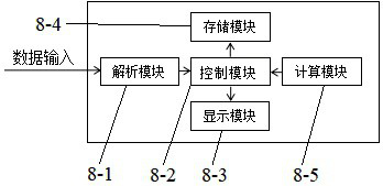
[0033] Such as figure 1 As shown, the present invention discloses a device for real-time testing and wireless transmission of rod pump power diagrams in pumping wells, including a battery pack 1, a magnetoacoustic energy converter 2, a system power supply 3, a displacement sensor 4, a circuit board 5, and a load The sensor 6, the housing 7 and the ground controller 8, the battery pack 1, the magnetoacoustic energy converter 2, the system power supply 3, the displacement sensor 4, the circuit board 5, and the load sensor 6 are all arranged inside the housing 7, wherein The ground controller 8 is arranged on the surface of the pumping well close to the wellhead, the battery pack 1 is electrically connected to the system power supply 3, the system power supply 3 is electrically connected to the displacement sensor 4 and the load sensor 6, and the displacement sensor 4 and the load sensor 6 are also respectively The circuit board 5 is connected, the circuit board 5 is electrically co

Embodiment 2

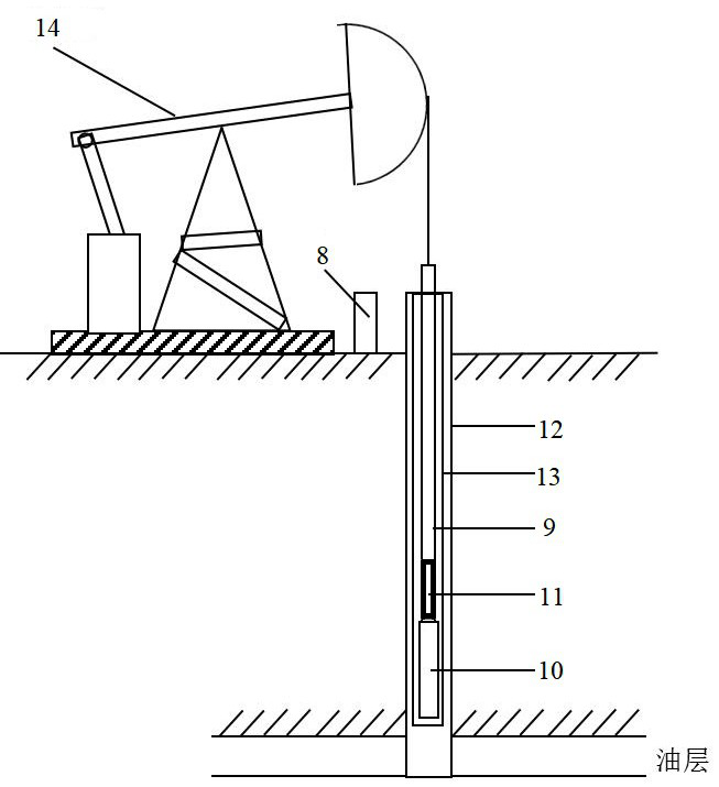
[0037] preferred, such as image 3 As shown, the casing 7 is a cylindrical sealing structure, wherein the upper end of the casing 7 is connected to the lower end of the sucker rod string 9 through a short joint, and the lower end of the casing 7 is connected to the upper end of the rod pump 10 through a short joint.

[0038] The real-time testing and wireless transmission device can also be installed between the sucker rod string 9 and the rod pump 10 through a collar.

[0039] Preferably, the diameter of the casing 7 is smaller than that of the rod pump 10 , and the diameter of the casing 7 is the same as that of the sucker rod string 9 .


PUM


Abstract

The invention discloses a real-time testing and wireless transmission device and method for a sucker-rod pump indicator diagram of a pumping well. The real-time testing and wireless transmission device comprises a battery pack, a magnetic acoustic energy converter, a system power supply, a displacement sensor, a circuit board, a load sensor, a shell and a ground controller, wherein the battery pack, the magnetic acoustic energy converter, the system power supply, the displacement sensor, the circuit board and the load sensor are arranged in the shell, the ground controller is arranged on the ground of the pumping well and is close to a wellhead, the battery pack is electrically connected with the system power supply, the system power supply is electrically connected with the displacement sensor and the load sensor, the displacement sensor and the load sensor are respectively connected with the circuit board, the circuit board is electrically connected with the magnetic acoustic energy converter, and the magnetic acoustic energy converter is in wireless connection with the ground controller.

Description


Claims


Application Information

Patent Timeline
Owner PETROCHINA CO LTD
Why Eureka
Try Eureka