A combined cooling and water braking system for a vehicle, and a method for cooling a propulsion device of a vehicle and water braking a pair of wheels of a vehicle

A propulsion device and a combined technology, which is applied in the combination of power plant cooling arrangement, cooling brake, power plant, etc., can solve the problems of heating and cooling systems, fuel cells that cannot be cooled, etc.

Pending Publication Date: 2021-05-07
VOLVO LASTVAGNAR AB
View PDF0 Cites 0 Cited by
  • Summary
  • Abstract
  • Description
  • Claims
  • Application Information

AI Technical Summary

Problems solved by technology

While water braking may work well with some types of engines, it may not work well with other types of engines that have low thermal inertia (especially if the cooling circuit does not include the motor) (in which case the water braking can significantly

Method used


Image

  • A combined cooling and water braking system for a vehicle, and a method for cooling a propulsion device of a vehicle and water braking a pair of wheels of a vehicle
  • A combined cooling and water braking system for a vehicle, and a method for cooling a propulsion device of a vehicle and water braking a pair of wheels of a vehicle
  • A combined cooling and water braking system for a vehicle, and a method for cooling a propulsion device of a vehicle and water braking a pair of wheels of a vehicle

Examples


Embodiment Construction

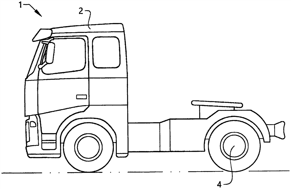
[0072] figure 1 Shown is a combined cooling and water braking system comprising at least one exemplary embodiment of the present invention ( figure 1 Not shown in the vehicle 1. Although the vehicle 1 is shown in the form of a truck, other types of vehicles may be provided according to the invention, such as buses, construction equipment or passenger cars.

[0073] The truck (vehicle 1 ) comprises a cab 2 in which the driver can operate the vehicle 1 . The vehicle 1 comprises a plurality of road wheels 4, here shown as two pairs of wheels, however in other embodiments there may be a different number of wheels, such as three, four or more pairs of wheels. Vehicles can have propulsion ( figure 1 not shown), the propulsion device is configured to generate propulsion power for the vehicle. The propulsion means may be, for example, an internal combustion engine, a battery powered electric motor, or a fuel cell powered motor.

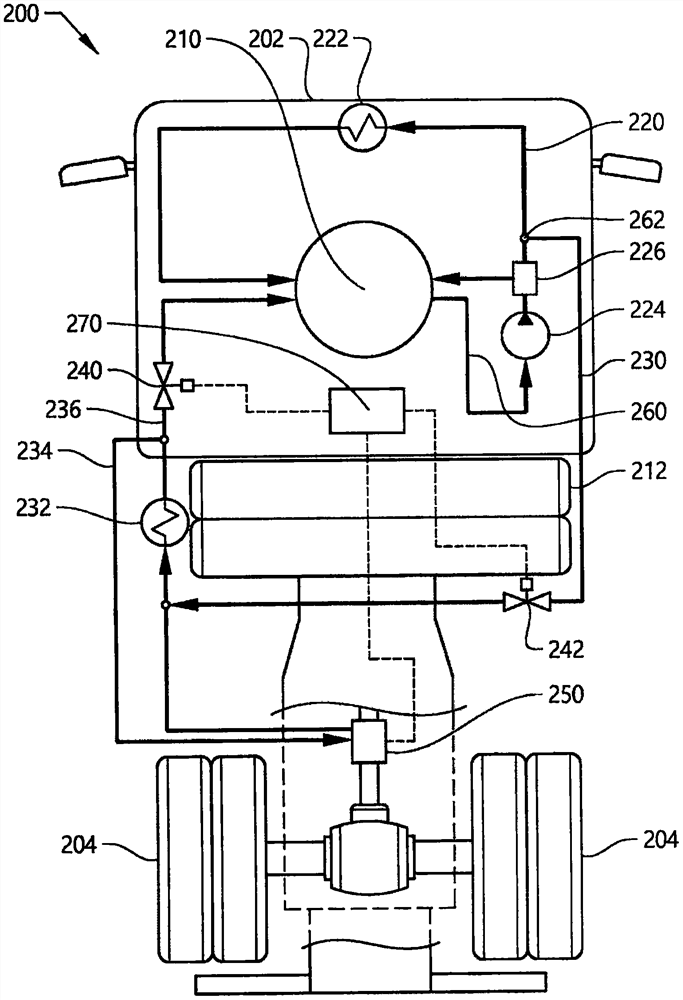
[0074] will target figure 2 The schematic illustrat


PUM


Abstract

There are provided a combined cooling and water braking system for a vehicle, and a method for cooling a propulsion device of a vehicle and water braking a pair of wheels of a vehicle. The system comprises a first water recirculation loop having a first heat exchanger configured to cool water flowing in the first water recirculation loop, the first water recirculation loop comprising a water conduit for transporting heat away from a propulsion device configured to generate a propulsion power for the vehicle. A second water recirculation loop having a second heat exchanger is configured to cool water flowing in the second water recirculation loop. A retarder is configured to be coupled to a pair of wheels of the vehicle. The second water recirculation loop may be selectively used for cooling the propulsion device and for providing water to the retarder for water braking.

Description


Claims


Application Information

Patent Timeline
Owner VOLVO LASTVAGNAR AB
Why Eureka
Try Eureka