Charging valve capable of rapidly injecting materials

A feeding valve and feeding valve technology, which is applied in the field of feeding valves for rapid-fire materials, can solve the problems of low switching efficiency, short service life, poor sealing, etc., and achieve the effects of prolonging service life, improving stability and reliability, and reducing wear

Pending Publication Date: 2021-05-14
永红保定铸造机械有限公司
View PDF0 Cites 0 Cited by
  • Summary
  • Abstract
  • Description
  • Claims
  • Application Information

AI Technical Summary

Benefits of technology

This patented design allows for better performance without any issues such as leakage or reduced lifespan due to poor designs used during manufacturing processes. It also includes an improved mechanism for prevention of materials getting inside while still allowing enough oil to be delivered through it's passageway. Additionally, this design has several technical benefits: it can reduce friction between parts when closed together, making sure no foreign substances get into them; and it provides full coverage over all areas where fluids are needed throughout its entire range of operation time.

Problems solved by technology

This patented describes an automated mold making system that uses continuous supply of sand material for producing parts quickly without any issues like leaks or other failures caused by previous systems' design. However, current methods have limitations with regards their effectiveness at maintaining reliable function over time due to wear on components.

Method used


Image

  • Charging valve capable of rapidly injecting materials
  • Charging valve capable of rapidly injecting materials

Examples


Embodiment Construction

[0022] In order to make the purpose, technical solution and advantages of the present application clearer, the technical solution of the present application will be clearly and completely described below in conjunction with specific embodiments of the present application and corresponding drawings. Apparently, the described embodiments are only some of the embodiments of the present application, rather than all the embodiments. Based on the embodiments in this application, all other embodiments obtained by persons of ordinary skill in the art without making creative efforts belong to the scope of protection of this application.

[0023] The technical solutions provided by various embodiments of the present application will be described in detail below in conjunction with the accompanying drawings.

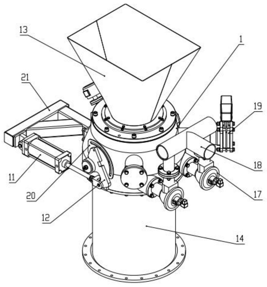
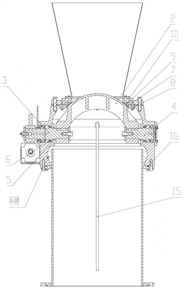
[0024] The embodiment of this specification provides a feeding valve for rapid-fire materials, such as figure 2 As shown, the feed valve includes a feed valve housing 1 , a rotating


PUM


Abstract

An embodiment of the invention discloses a charging valve capable of rapidly injecting materials. The charging valve comprises a charging valve shell, a rotating hemisphere, a driving shaft, a driven shaft and an inflatable sealing rubber ring, wherein the rotating hemisphere is connected to the charging valve shell through the driving shaft and the driven shaft, and the rotating hemisphere is hermetically connected to the charging valve shell through the inflatable sealing rubber ring; and the driving shaft is hermetically connected to the charging valve shell, and the driven shaft is hermetically connected to the charging valve shell. According to the charging valve, a rotary hemispherical sealing structure is adopted, and the driving shaft and the driven shaft adopt dust-proof and inverted sealing structures, so that the defects that an existing structure is not tight in sealing and easy to leak materials are overcome, the stability and the reliability are improved, the service life is prolonged, and it can be ensured that lubricating oil and impurities are discharged through an inverted sealing ring when the lubricating oil is supplemented. The inflatable sealing rubber ring is in a retractable type, so that the inflatable sealing rubber ring is completely separated when the rotating hemisphere moves, the abrasion between the inflatable sealing rubber ring and the rotating hemisphere is reduced, and the service life is effectively prolonged.

Description


Claims


Application Information

Patent Timeline
Owner 永红保定铸造机械有限公司
Why Eureka
Try Eureka