Control method resonant circuit of and terminal equipment

A technology of a resonant circuit and a control method, which is applied in the control/regulation system, electrical components, regulating electrical variables, etc., can solve the problems of high stress on the switch tube, easy damage to the switch tube, and excessive energy in the resonant cavity.

Inactive Publication Date: 2021-05-18
SHENZHEN KEHUA HENGSHENG TECH
View PDF7 Cites 0 Cited by
  • Summary
  • Abstract
  • Description
  • Claims
  • Application Information

AI Technical Summary

Problems solved by technology

[0004] In view of this, the embodiment of the present invention provides a control method and terminal equipment for a resonant circuit to solve the problem that in the prior art, when the drive is turned off, the energy of the resonant cavity is too large to effectively release the energy, the stress of the switch tube is too large, and it is easy to The problem of damaging the switch tube

Method used


Image

  • Control method resonant circuit of and terminal equipment
  • Control method resonant circuit of and terminal equipment
  • Control method resonant circuit of and terminal equipment

Examples


Embodiment Construction

[0023] In the following description, specific details such as specific system structures and technologies are presented for the purpose of illustration rather than limitation, so as to thoroughly understand the embodiments of the present application. It will be apparent, however, to one skilled in the art that the present application may be practiced in other embodiments without these specific details. In other instances, detailed descriptions of well-known systems, devices, circuits, and methods are omitted so as not to obscure the description of the present application with unnecessary detail.

[0024] In order to illustrate the technical solutions of the present invention, specific examples are used below to illustrate.

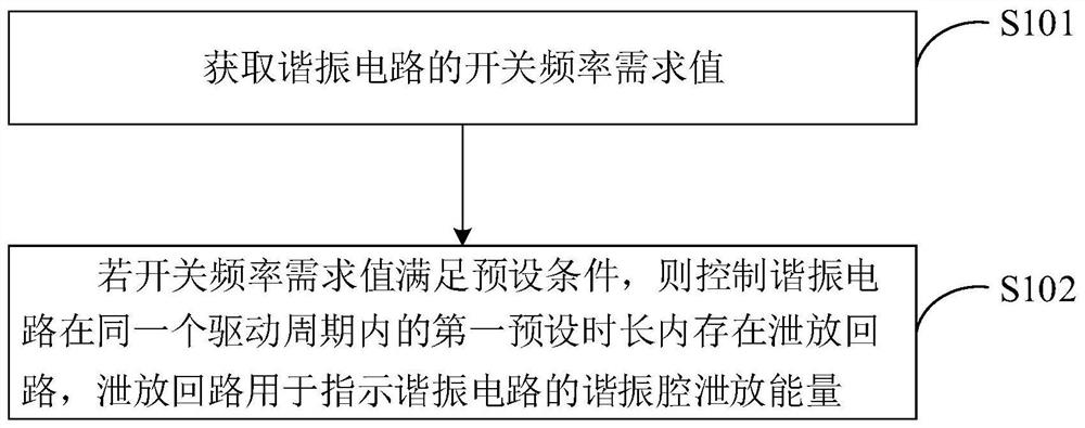
[0025] figure 1 It is a schematic flowchart of the realization of the method for controlling the resonant circuit provided by an embodiment of the present invention. For the convenience of description, only the parts related to the embodiment of the prese...


PUM


Abstract

The invention is suitable for the technical field of switching power supplies, and discloses a control method of a resonant circuit and terminal equipment, and the method comprises the steps: obtaining a switching frequency demand value of the resonant circuit; if the switching frequency demand value meets a preset condition, the resonant circuit is controlled to have a discharge loop within a first preset duration in the same driving period, and the discharge loop is used for indicating a resonant cavity of the resonant circuit to discharge energy; wherein when the switching frequency demand value meets the preset condition, the resonant circuit is controlled in a mode of adjusting the switching frequency, so that the demand of the output voltage of the resonant circuit cannot be met, and the control mode of the resonant circuit is changed into a mode of adjusting the driving duty ratio. The energy in the resonant cavity is released through the discharge loop, the energy can be effectively released, the stress of the switching tube is reduced, the switching tube is prevented from being damaged, and the reliability of the switching tube can be improved.

Description

technical field [0001] The invention belongs to the technical field of switching power supplies, and in particular relates to a method for controlling a resonant circuit and terminal equipment. Background technique [0002] For the resonant circuit, in order to achieve a wider range of output voltage, usually when the switching frequency demand value is in the low-frequency pulse frequency range of 80-250kHz, the switching frequency is adjusted to achieve monotonic voltage regulation of the output voltage. Due to the output characteristics of the resonant circuit, when the switching frequency is greater than the resonant frequency, the step-down characteristics of the resonant circuit tend to be gentle. Therefore, when the switching frequency demand value is greater than 250kHz in the high-frequency pulse frequency range, continue to increase the switching frequency, the output The magnitude of the voltage reduction cannot meet the demand of a wide range of output voltage, s...

Claims


Application Information

Patent Timeline
IPC IPC(8): H02M3/335H02M1/32H02M1/38
CPCH02M1/32H02M1/38H02M3/33569Y02B70/10
Inventor 雷爽林剑勇张晓博刘旭明付君宇
Owner SHENZHEN KEHUA HENGSHENG TECH
Why Eureka
Try Eureka