Gas supply system, gas supply method and hydrogen refueling station
A gas supply system and gas supply technology, applied in the direction of gas/liquid distribution and storage, container filling method, container discharge method, etc., can solve the problems of restricting the promotion and application of hydrogen refueling stations, large layout spacing, and limited application , to achieve the effect of promoting promotion and application, reducing floor space, and reducing the frequency of start and stop
- Summary
- Abstract
- Description
- Claims
- Application Information
AI Technical Summary
Problems solved by technology
Method used
Image

Examples
Embodiment 1
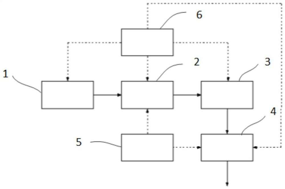
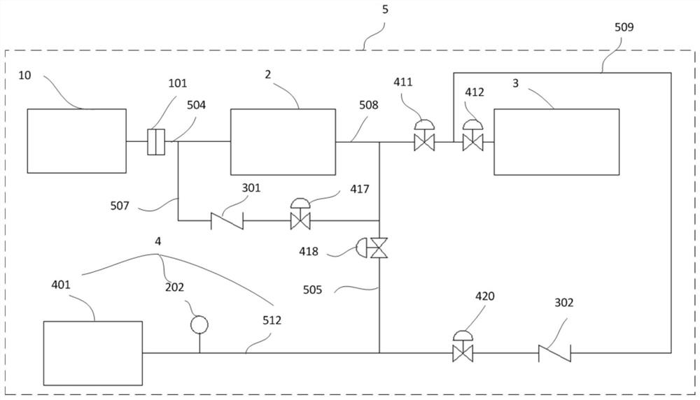
[0149] This embodiment provides a gas supply system. See image 3 , the gas supply system includes: an unloading system 1, a compressor 2, a hydrogen storage tank 3, a filling system 4, and a control system 5; the gas source device 10 communicates with the compressor 2 through an unloading pipeline 504, and the unloading The first breakaway valve 101 in the system 1 is located on the unloading pipeline 504; the outlet end of the compressor 2 communicates with the gas storage tank 3 through the compressor outlet pipeline 508; the gas storage tank 3 passes through the first The outlet line 509 of the gas storage tank communicates with the filling system 4 ; the outlet end of the compressor 2 communicates with the filling system 4 through the first compressor direct charging line 505 . A second one-way valve 302 and a tenth shut-off valve 420 are provided on the gas outlet pipeline 509 of the first gas storage tank. A first shut-off valve 411 is provided on the compressor outlet l
Embodiment 2
[0151] This embodiment provides a gas supply method. See figure 1 and image 3 , the gas supply method includes the following steps:
[0152] A. The gas unloading system 1 transfers the hydrogen in the gas source device 10 to the compressor 2 .
[0153] B. The hydrogen gas pressurized by the compressor 2 is charged into the gas storage tank 3 for storage.
[0154] C, the hydrogen in the gas storage tank 3 is filled to the hydrogen filling device through the filling system 4.
[0155] D. The control system 5 monitors the hydrogen pressure in the hydrogen filling equipment, the hydrogen pressure in the gas storage tank 3, and the hydrogen pressure in the gas source equipment 10, and also controls the gas unloading system 1. The compressor 2 and the filling system 4 are turned on and off.
[0156] E. If the control system 5 detects that the hydrogen pressure in the hydrogen storage tank 3 is lower than the first preset value, the control system 5 starts the compressor 2, and th
Embodiment 3
[0159] This embodiment provides a hydrogen refueling station. The hydrogen refueling station includes the gas supply system in Embodiment 1. The gas supply system is jointly built on the basis of the gas station.
PUM
 Abstract
Description
Claims
Application Information
 - R&D Engineer
- R&D Manager
- IP Professional
- Industry Leading Data Capabilities
- Powerful AI technology
- Patent DNA Extraction
Browse by: Latest US Patents, China's latest patents, Technical Efficacy Thesaurus, Application Domain, Technology Topic.
© 2024 PatSnap. All rights reserved.Legal|Privacy policy|Modern Slavery Act Transparency Statement|Sitemap