Rotary switch with energy storage mechanism
A technology of energy storage mechanism and rotary switch, which is applied in the direction of electric switches, electrical components, circuits, etc., can solve the problems of large photovoltaic power station area, long distance, and difficulty in quickly cutting off circuits, and achieve the effect of convenient operation
- Summary
- Abstract
- Description
- Claims
- Application Information
AI Technical Summary
Benefits of technology
Problems solved by technology
Method used
Image

Examples
Embodiment 1
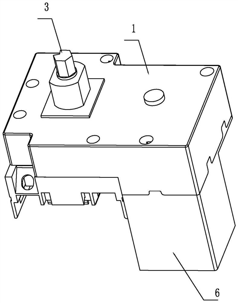
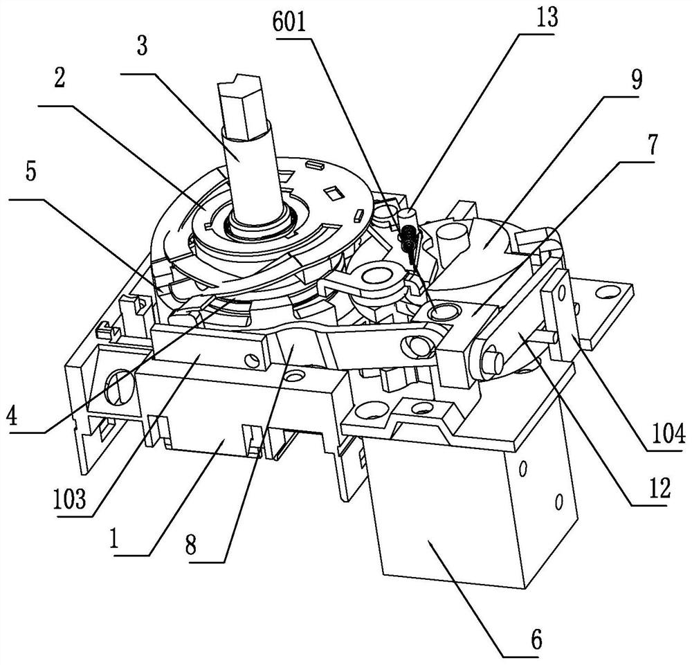
[0049] Such as Figure 1-2 As shown, this embodiment provides a rotary switch, which includes a housing 1, an operating mechanism and an energy storage mechanism disposed in the housing 1, and an electromagnetic drive mechanism 6, and the energy storage mechanism is located on the side of the operating mechanism. Specifically, the housing 1 includes upper and lower parts, and the upper and lower parts are assembled to form the housing 1 in which the operating mechanism and the energy storage mechanism are disposed in the inner cavity.
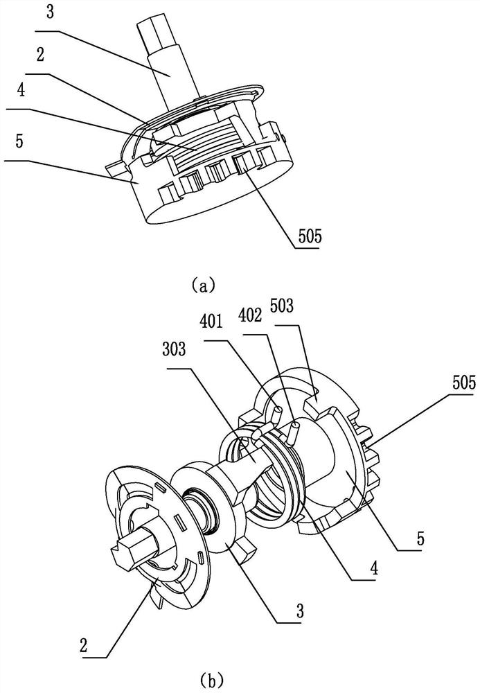
[0050] Such as Figure 3-5 As shown, the operating mechanism includes a snap ring assembly 2, an operating shaft 3, a first energy storage element 4, and an operating swivel seat 5 arranged in sequence. The operating shaft 3 is concentrically arranged with the operating swivel seat 5, and the first An energy storage element 4 is arranged between the operating shaft 3 and the operating swivel seat 5, and its two ends respectively abut and cooperat
Embodiment 2
[0070] This embodiment provides a rotary switch, which includes a housing 1, an operating mechanism and an energy storage mechanism disposed in the housing 1, and an electromagnetic drive mechanism 6, and the energy storage mechanism is located on one side of the operating mechanism.
[0071] The operating mechanism includes a snap ring assembly 2, an operating shaft 3, a first energy storage element 4, and an operating swivel seat 5 arranged in sequence, such as Figure 16 As shown, the operating shaft 3 is provided with a positioning post 302 for concentric positioning with the operating swivel seat 5, a first torsion spring driving arm 303 for cooperating with the first torsion arm 401 of the first energy storage element 4, and When lifting the circlip unlocking block 301 of the second circlip 204, the first torsion spring driving arm 303 partially extends in the direction of closing and rotating to form a bump, and the bump is provided with an energy storage limit groove 305,
Embodiment 3
[0080] This embodiment provides a rotary switch, which includes a housing 1 , an operating mechanism and an energy storage mechanism disposed in the housing 1 , and also includes an electromagnetic drive mechanism 6 , and the energy storage mechanism is located on one side of the operating mechanism.
[0081] The operating mechanism includes a snap ring assembly 2, an operating shaft 3, a first energy storage element 4, and an operating swivel seat 5 arranged in sequence, wherein the structure of the operating shaft 3 is the same as that of Embodiment 1, wherein the snap ring assembly 2, the first The structures of the energy storage element 4 and the operating swivel seat 5 are the same as those of the snap spring assembly 2, the first energy storage element 4, and the operating swivel seat 5 in Embodiment 1. The snap ring assembly 2, the operating shaft 3, and the first energy storage element 4. The matching structure between the operating swivel seats 5 is also the same as that
PUM
 Abstract
Description
Claims
Application Information
 - R&D Engineer
- R&D Manager
- IP Professional
- Industry Leading Data Capabilities
- Powerful AI technology
- Patent DNA Extraction
Browse by: Latest US Patents, China's latest patents, Technical Efficacy Thesaurus, Application Domain, Technology Topic.
© 2024 PatSnap. All rights reserved.Legal|Privacy policy|Modern Slavery Act Transparency Statement|Sitemap