Forward pushing type hip joint reduction device

A reset device and hip joint technology, applied in the direction of hip joints, joint implants, joint implants, etc., can solve problems such as difficult reset, achieve the effect of reducing pain, reducing work burden, and high reset efficiency

Active Publication Date: 2021-07-09
山东大学齐鲁医院(青岛)
View PDF8 Cites 0 Cited by
  • Summary
  • Abstract
  • Description
  • Claims
  • Application Information

AI Technical Summary

Benefits of technology

This patented technology describes an improved version of the pull back type knee reversion system for correcting leg length disabilities caused by necrotic or osteonecrosis (ostomy). In summary, these improvements include improving flexibility, ease of use, safety measures against injury, and enabling greater adjustment options compared to previous systems.

Problems solved by technology

This patents describes different ways to make up hip replacements by replacing only one part (the ball) from the socket to another part called the cup-shaped portion. However, there are technical problem addressed before this new design becomes commercially available due to its high risk of causing painful complications such as perforation of blood vessels caused by pressure on nerves inside them.

Method used


Image

  • Forward pushing type hip joint reduction device
  • Forward pushing type hip joint reduction device
  • Forward pushing type hip joint reduction device

Examples


Embodiment

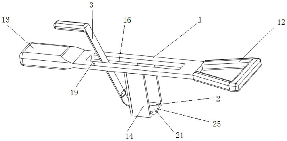
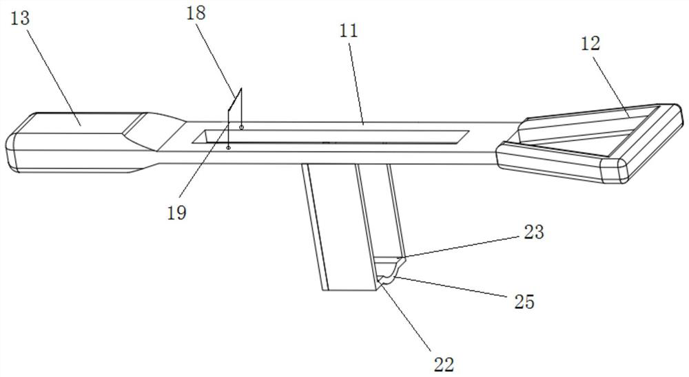
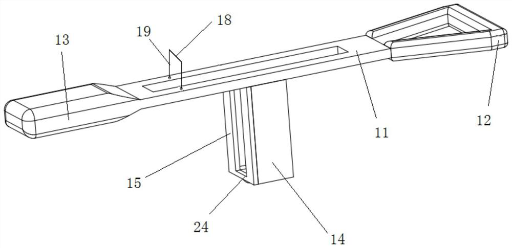
[0051] This embodiment provides a forward push type hip joint reduction device, such as Figure 1-3 As shown, it includes: a main bracket 1, a supporting plate 2 and a front push piece 3. in:

[0052]The main stand 1 includes a main stand body 11 , a first handle 12 disposed at one end of the main stand body 11 , and a second handle 13 disposed at the other end of the main stand body 11 . The main bracket main body 11 is used to connect other components, and the first hand-held part 12 and the second hand-held part 13 are convenient to be held by the same doctor, or two or more doctors, to lift the main bracket 1; One of the hand-held parts is supported at a certain position, and the main support 1 is assisted to be lifted by utilizing the principle of leverage.

[0053] The supporting plate 2 is arranged under the main bracket 1, fixedly connected with the middle part of the main bracket 1, and is suitable for being inserted under the femoral head.

[0054] like Figure 4 As


PUM


Abstract

The invention provides a forward pushing type hip joint reduction device which comprises a main support with a certain length; the supporting plate is arranged below the main support, is fixedly connected with the middle part of the main support, and is suitable for being inserted below the femoral head; and the front pushing part is suitable for pushing the femoral head down from the supporting plate. Compared with a cylindrical repositor in the prior art, the forward pushing type hip joint repositor changes the force application direction, an existing cylindrical repositor can only be pushed forwards in the axial direction, consequently, the femoral head abuts against the rear edge of the acetabulum and is difficult to span, and the repositor firstly lifts the femoral head till the femoral head is higher than the rear edge of the acetabulum, and then the femoral head is pushed forwards in the axial direction. Compared with the prior art, according to the technical scheme, operation is easier, the reduction efficiency is higher, the workload of medical staff is relieved, and the pain of a patient is also relieved.

Description


Claims


Application Information

Patent Timeline
Owner 山东大学齐鲁医院(青岛)
Why Eureka
Try Eureka