Phase-locked loop

A phase-locked loop and voltage tuning technology, which is applied in the field of phase-locked loops, can solve the problems of long time and time consumption, and achieve the effect of shortening the sub-band selection time

Pending Publication Date: 2021-07-09
江苏集萃智能集成电路设计技术研究所有限公司
View PDF5 Cites 0 Cited by
  • Summary
  • Abstract
  • Description
  • Claims
  • Application Information

AI Technical Summary

Problems solved by technology

In low-cost applications, the first solution has a simple circuit, and its high reliability has won the favor of most designers, but its main problem is that it takes a lon

Method used


Image

  • Phase-locked loop
  • Phase-locked loop
  • Phase-locked loop

Examples


Embodiment Construction

[0023] The present invention is described in further detail now in conjunction with accompanying drawing. These drawings are all simplified schematic diagrams, which only illustrate the basic structure of the present invention in a schematic manner, so they only show the configurations related to the present invention.

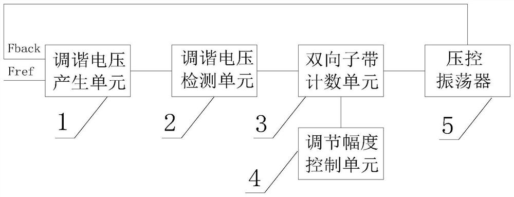
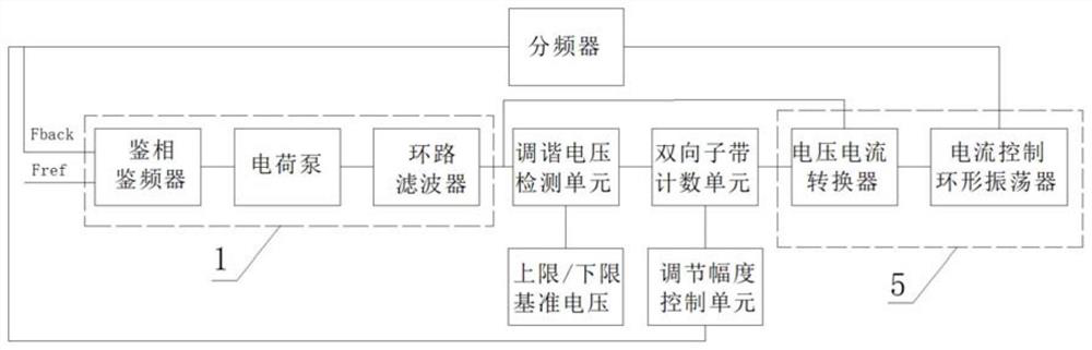
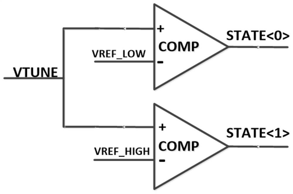
[0024] Such as figure 1 As shown, the phase-locked loop includes a tuning voltage generation unit 1, a tuning voltage detection unit 2, a bidirectional sub-band counting unit 3, an adjustment amplitude control unit 4, and a voltage-controlled oscillator 5. The tuning voltage generation unit 1 is based on the input reference frequency Fref The phase difference with the output frequency Fback of the voltage-controlled oscillator 5 generates a tuning voltage VTUNE, and the tuning voltage detection unit 2 inputs a counting direction control signal to the bidirectional sub-band counting unit 3 according to the size of the tuning voltage VTUNE, and the bidirectional su


PUM


Abstract

The invention relates to the technical field of electronic communication, and discloses a phase-locked loop, which comprises a tuning voltage generation unit, a tuning voltage detection unit, a bidirectional sub-band counting unit, an adjustment amplitude control unit and a voltage-controlled oscillator; in actual use, the output frequency sub-band of the voltage-controlled oscillator is controlled through an output signal of the bidirectional sub-band counting unit; then an output signal of the bidirectional sub-band counting unit is determined by a counting direction and an adjusting amplitude, the counting direction is input by the tuning voltage detection unit, and the adjusting amplitude is input by the adjusting amplitude control unit, so that the frequency of the phase-locked loop does not need to be adjusted one by one; and therefore, the sub-band selection time of the phase-locked loop can be shortened according to the multi-stage adjustment of the difference between the reference frequency and the output frequency of the voltage-controlled oscillator.

Description


Claims


Application Information

Patent Timeline
Owner 江苏集萃智能集成电路设计技术研究所有限公司
Why Eureka
Try Eureka