Surface-strengthened inner step shaft inner hole precision forming process

A surface strengthening and precision forming technology, applied in the field of machining, can solve the problems of damaged mandrel forming, long cycle, low efficiency, poor straightness, etc., and achieve the effect of applying surface compressive stress, improving fatigue resistance and improving straightness.

Active Publication Date: 2021-07-16
XI AN JIAOTONG UNIV +1
View PDF7 Cites 0 Cited by
  • Summary
  • Abstract
  • Description
  • Claims
  • Application Information

AI Technical Summary

Benefits of technology

This patented technology improves on existing methods for machining holes inside metal parts by providing an internal cavity with a special shape called a mandrel or die used instead of traditional tools like cutting bits. By doing this, it simplifies manufacturing processes while also enhancing its precision and performance over time. Additionally, these technical improvements help prevent issues related to productivity and reliability caused by poorly formed surfaces when subjected to high levels of external forces (such as impact). Overall, they contribute towards better efficiency and cost savings associated with production lines.

Problems solved by technology

This patented technical problem addressed by this patents relates to machining complicated internal surfaces like these components during aircraft engines' development stages because they require accurate dimensions and have hidden drilled holes (BH) inside them. Current methods involve multiple steps involving different tools, leading to difficulties in maintaining consistently good results despite changes made over many hours.

Method used


Image

  • Surface-strengthened inner step shaft inner hole precision forming process
  • Surface-strengthened inner step shaft inner hole precision forming process
  • Surface-strengthened inner step shaft inner hole precision forming process

Examples


Embodiment 1

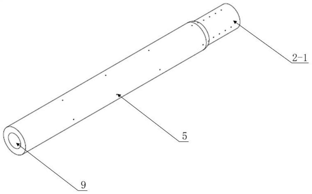
[0044] Embodiment 1, using the integral mandrel 2-1, a surface-strengthened internal step shaft inner hole precision forming process, including the following steps:

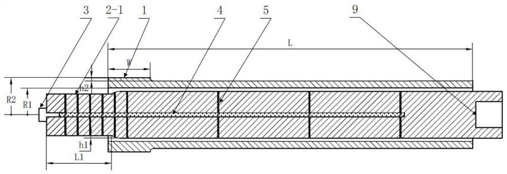
[0045] 1) Design blank: refer to image 3 , the design length of blank 1 is L, the design inner and outer diameters are R1 and R2 respectively, the length of the raised part of the blank is W, and the height of the raised part is h2; Step length L1; billet 1 design reference ratio W:L1:(h2-h1)=(6~7):(9~10):1, the more refined billet 1 size design needs to be based on finite element simulation and experimental experience results Pick;

[0046] 2) Remove the lubricant plug 3 of the integral mandrel 2-1, pump lubricant into the lubricant main channel 4 of the integral mandrel 2-1, so that the pumped lubricant fills the lubricant main channel 4, lubricant In the inner area formed by the shunt channel 5, after the pumping is completed, the lubricant plug 3 is installed to prevent the lubricant from leaking;

[0047]3)

Embodiment 2

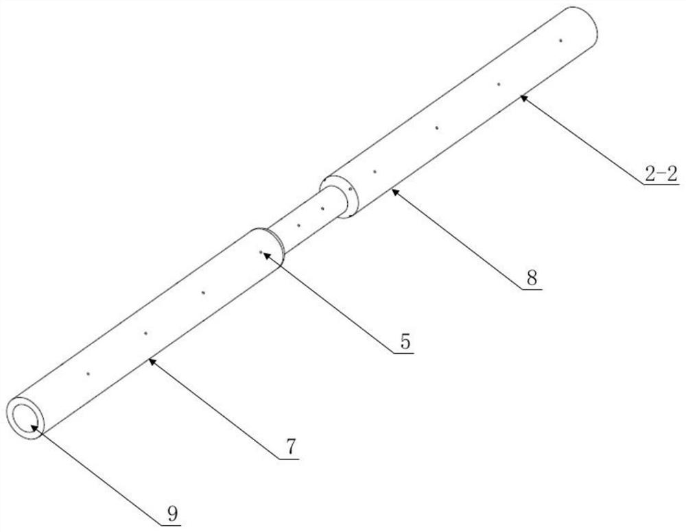
[0051] Embodiment 2, using the split mandrel 2-2, a surface-strengthened internal step shaft inner hole precision forming process, including the following steps:

[0052] 1) Design blank: refer to Figure 6 , the design length of blank 1 is L, the design inner and outer diameters are R1 and R2 respectively, the length of the raised part of the blank is W, and the height of the raised part is h2; -2 step length L1; billet 1 design reference ratio W:L1:(h2-h1)=(6~7):(9~10):1, the more refined billet 1 size design needs to be based on finite element simulation and experimental experience results to fetch;

[0053] 2) Remove the lubricant plug 3 of the split mandrel 2-2, pump lubricant into the main lubricant channel 4 of the split mandrel 2-2, and make the pumped lubricant fill the main lubricant channel 4, The internal area formed by the lubricant flow channel 5, after the pumping is completed, the lubricant plug 3 is installed to prevent the lubricant from leaking;

[0054] 3)


PUM


Abstract

The invention discloses a surface-strengthened inner step shaft inner hole precision forming process. The process comprises the following steps that firstly, a blank is designed, and a lubricant is pumped into an internal area formed by a lubricant main runner and lubricant sub-runners of a mandrel; the mandrel and the blank are assembled, a rotary swaging machine is mounted through a mounting hole at the rear portion of the mandrel, the mandrel and the blank are subjected to high-frequency forging of a forging die together, and a large inner hole is formed through rotary swaging; then the positions of the mandrel and the blank are adjusted, rotary swaging is started from the protruding position of the blank, and a small inner hole is formed through rotary swaging; a die for strengthening is replaced and used, the rotary swaging machine is assembled, the rotating speed of a motor of the rotary swaging machine is reduced, so that the impact energy of the die is reduced, the overall surface of the blank subjected to inner hole rotary swaging is forged, uniform pressure stress is added to the surface of the blank, and the surface secondary strengthening effect similar to shot blasting impact is achieved; and finally, a workpiece is taken away. The inner hole forming can be guaranteed, the surface of a shaft can be effectively strengthened, and the fatigue strength is improved.

Description


Claims


Application Information

Patent Timeline
Owner XI AN JIAOTONG UNIV
Why Eureka
Try Eureka