Double-layer sealing structure

A double-layer sealing, graphite sealing technology, applied in shaft sealing, engine sealing, valve details, etc., can solve the problems of increased working steam consumption, low suction pressure, large air leakage, etc., and achieve wide application prospects , The effect of improving air leakage and reducing usage

Pending Publication Date: 2021-07-23
中国船舶重工集团公司第七0四研究所
View PDF0 Cites 0 Cited by
  • Summary
  • Abstract
  • Description
  • Claims
  • Application Information

AI Technical Summary

Problems solved by technology

Although the sealing groove structure can play a certain sealing role, the use of the sealing groove cannot prevent the flow of high-pressure steam to the pumping chamber through the gap between the shaft holes
And the structure also has a large amount of air leakage
The air extraction system needs to consume a certain amount of working steam to achieve a lower suction pressure, and a larger leakage will lead to an increase

Method used


Image

  • Double-layer sealing structure
  • Double-layer sealing structure
  • Double-layer sealing structure

Examples


Example Embodiment

[0025] The present invention will be further described below with reference to the accompanying drawings.

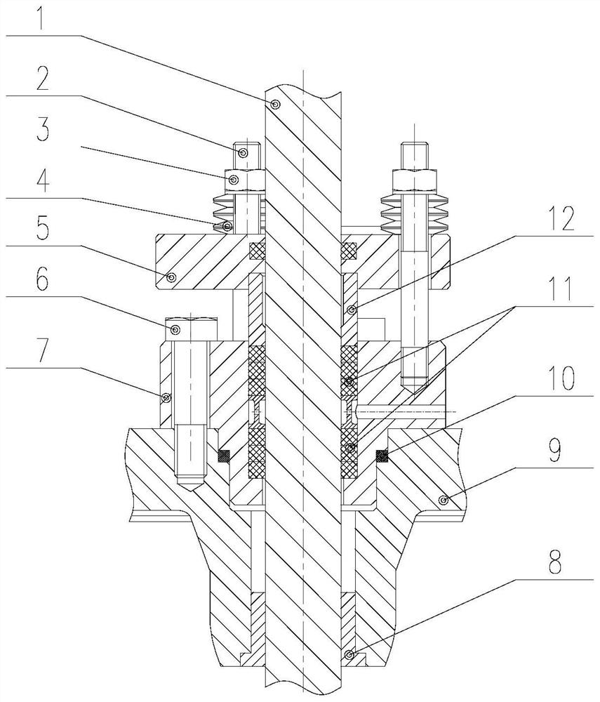
[0026] like figure 2 As shown, the sealing effect of the double layer sealing structure of the present invention is mainly based on the sealing ring and the graphite sealing filler.

[0027] The structure includes a valve stem 1, the stud 2, the nut 3, the disc spring 4, the upper compression cover 5, the bolt 6, the lower compression cover 7, the lower bushing 8, the valve body 9, sealing ring 10, graphite sealing filler 11, Bushne 12. The lower end bushing 8 is contained in the lower end of the valve body 9, and the upper end is fixed to the lower compression cover 7 by the bolt 6, and the upper surface of the lower compression cover 7 is connected by the stud 2, the nut 3 and the disc spring 4, the valve stem 1 and the valve body The lower bushing 8 in the 9 is mounted, and the multilayer graphite sealing filler 11 is provided between the valve stem 1 and the lower pressure


PUM


Abstract

The invention relates to a double-sealing structure. The double-layer sealing structure is provided with a valve rod and a valve body connected with the valve rod in a matched mode, wherein a lower gland is fixedly connected into the upper end of the valve body in a sealed mode, the upper end of the lower gland is connected with an upper gland through three fastening structures, multiple layers of graphite sealing filler are arranged between the valve rod and the lower gland for sealing, the lower end of the upper gland is connected with the graphite sealing filler through an upper lining, and the graphite sealing filler in the lower gland is tightly pressed by the upper gland through three fastening structures and the upper lining. The use of the structure can solve the problem of air leakage in an existing valve rod sealing structure, reduces the use amount of working steam of a steam seal air exhaust system, and has a wide application prospect in high-pressure steam machinery.

Description


Claims


Application Information

Patent Timeline
Owner 中国船舶重工集团公司第七0四研究所
Why Eureka
Try Eureka