Method for machining high-precision pipe hole through radial drilling machine

A radial drilling machine, high-precision technology, applied in the direction of boring machine/drilling machine parts, boring/drilling, metal processing equipment, etc., can solve the problems of drilling progress decline, drill pipe vibration, etc., to achieve vibration amplitude reduction, Improve the degree of automation and improve the effect of accuracy

Active Publication Date: 2021-08-06
NAVAL AERONAUTICAL UNIV
View PDF10 Cites 1 Cited by
  • Summary
  • Abstract
  • Description
  • Claims
  • Application Information

AI Technical Summary

Problems solved by technology

[0004] In view of the deficiencies in the use of the existing radial drilling machine proposed in the background technology, the present invention provides a method for processing high-precision pipe holes using a radial drilling machine, which has the advantages of stabilizing the attitude of the drill rod and improving the drilling progress. It solves the problem that the drill pipe of traditional equipment is prone to vibration, which leads to the decline of drilling progress

Method used


Image

  • Method for machining high-precision pipe hole through radial drilling machine
  • Method for machining high-precision pipe hole through radial drilling machine
  • Method for machining high-precision pipe hole through radial drilling machine

Examples


Example Embodiment

[0027] The following will clearly and completely describe the technical solutions in the embodiments of the present invention with reference to the accompanying drawings in the embodiments of the present invention. Obviously, the described embodiments are only some of the embodiments of the present invention, not all of them. Based on the embodiments of the present invention, all other embodiments obtained by persons of ordinary skill in the art without making creative efforts belong to the protection scope of the present invention.

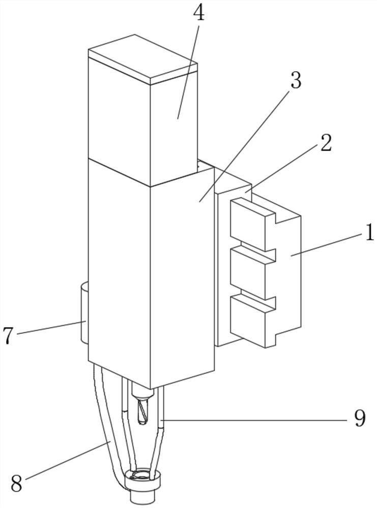
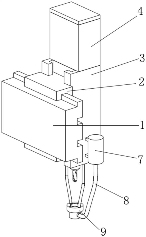
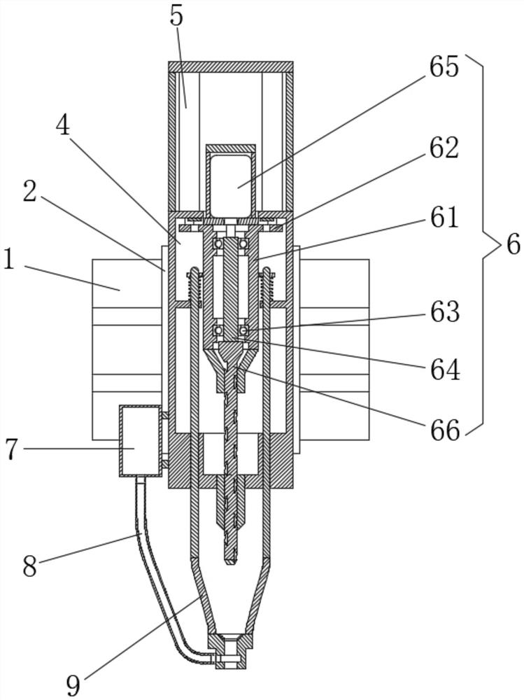
[0028] see Figure 1-8, a method for machining high-precision pipe holes using a radial drilling machine, comprising a transverse travel rod 1, a longitudinal travel rod 2 is movably installed on one side of the lateral travel rod 1, and a travel device 3 is movably installed on one side of the longitudinal travel rod 2, Stroke device 3 comprises stroke chamber 31, and trigger block 32 is fixedly installed on the position near the two sides of the t


PUM


Abstract

The invention relates to the technical field of machining, and discloses a method for machining a high-precision pipe hole through a radial drilling machine. The method comprises a transverse stroke rod, wherein a longitudinal stroke rod is movably installed at one side of the transverse stroke rod, a stroke device is movably installed at one side of the longitudinal stroke rod, and a power bin is fixedly installed at the top of the stroke device; and a limiting device is blocked by a workpiece at the moment and cannot continue to move, so that the limiting device can move in the vertical upward direction in the figure 5, and at the moment, the axis of limiting rods and the axis of trigger blocks are located on the same center line. The tops of the limiting rods can make contact with the bottoms of the trigger blocks, the output ends of the trigger blocks are connected with the input ends of hydraulic telescopic rods in a signal connection manner, and the hydraulic telescopic rods are triggered to work at the moment, so that the stroke limit of the stroke device is limited, and the automation degree of the device is improved; and meanwhile, the problem of faults caused by stroke overrun of the stroke device is also avoided, and the running stability of the device is improved.

Description


Claims


Application Information

Patent Timeline
Owner NAVAL AERONAUTICAL UNIV
Why Eureka
Try Eureka