Self-cleaning kneading reactor

A reactor, self-cleaning technology, applied in chemical/physical/physicochemical fixed reactors, chemical instruments and methods, chemical/physical/physicochemical processes, etc. The industrial application of screw extruders and the inability to update the interface can achieve the effects of improving heat transfer efficiency and mixing efficiency, reducing thermal loss, and narrow residence time distribution

Pending Publication Date: 2021-08-31
江苏胜开尔工业技术有限公司
View PDF0 Cites 4 Cited by
  • Summary
  • Abstract
  • Description
  • Claims
  • Application Information

AI Technical Summary

Benefits of technology

This patented design allows for efficient mixings between two different types of fluids without causing any residue left behind due to their interaction with one another. It uses multiple pairs of helixes called E-shaped bifurcation blades attached together along its length axis instead of just single ones like traditional designs. These wings help distribute the load evenly over long distances, reducing friction and allowing for better mixing performance. Additionally, it achieves this through reverse movements of the vane plate and twist rods, which helps keep solid particles moving smoothly. Overall, these technical featments enhance the overall function of the stagger rotary mill machine described earlier in the patents.

Problems solved by technology

This patented technical solution involves developing a new type of chemical reactor called a teaser mix machine (TMC). These machines use specialized tools like spirals to improve their performance without damaging any materials being processed. They work better because they reduce pressure drop during production compared to traditional methods such as batch processes while still maintaining good liquid properties. Additionally, these TCMR systems allow for controlled cool down periods between stages where the material's viscid nature prevents proper functioning.

Method used


Image

  • Self-cleaning kneading reactor
  • Self-cleaning kneading reactor
  • Self-cleaning kneading reactor

Examples


Embodiment Construction

[0041] The present invention will be further described below in conjunction with the accompanying drawings and embodiments.

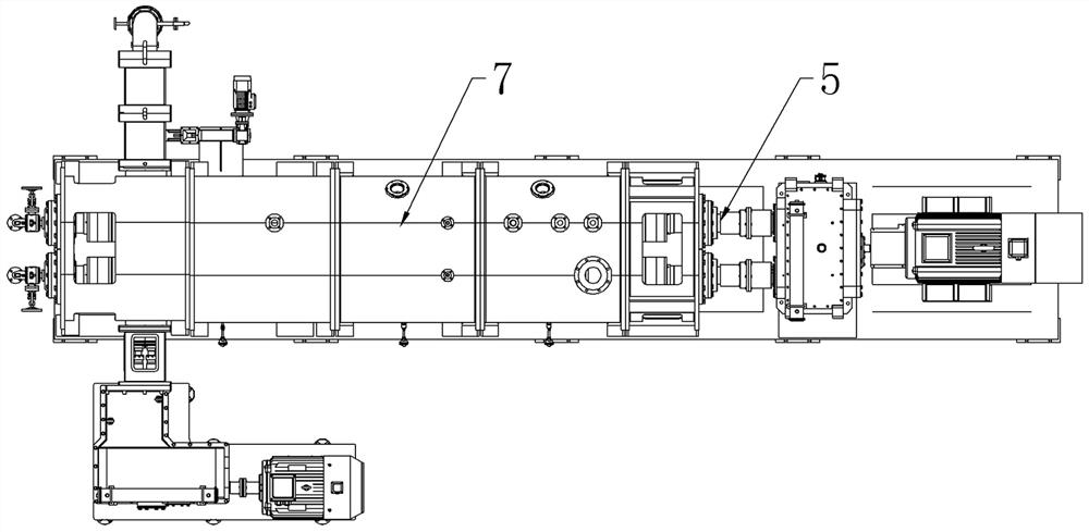
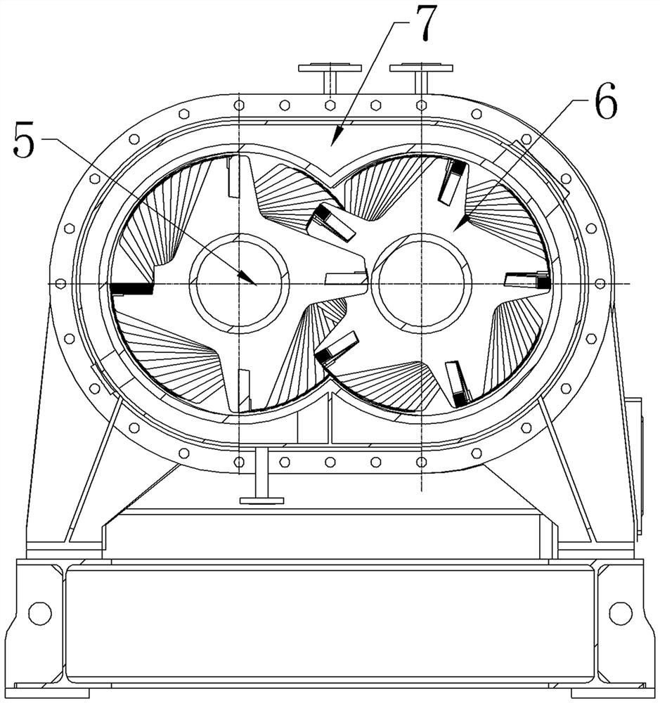
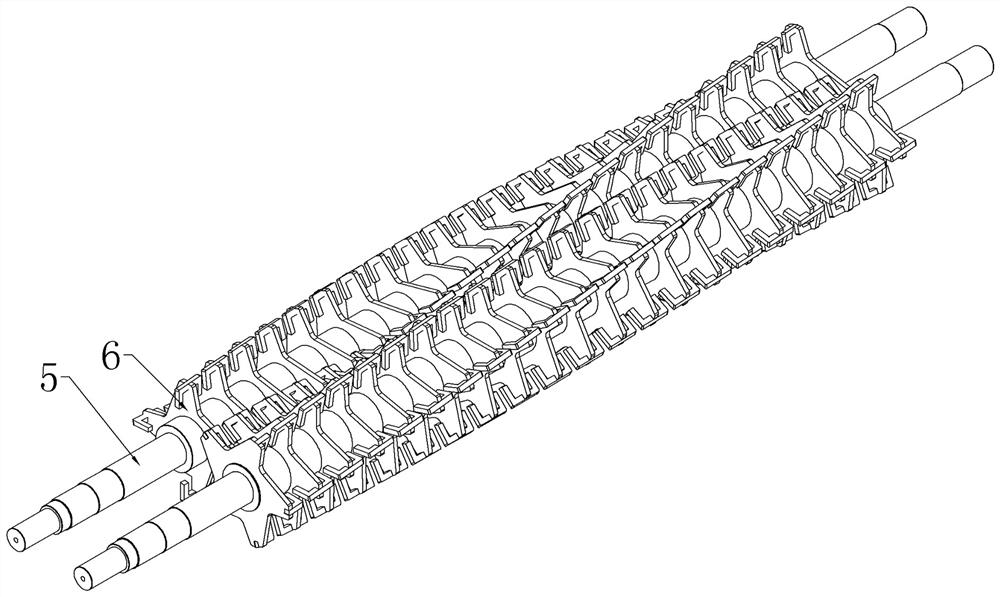
[0042] Such as Figure 1-5 Shown: a self-cleaning kneading reactor, including a cylinder 7 and a stirring rotor 5, inside the cylinder 7 with an "8" cross-section, there are two stirring rotors 5 arranged in parallel in pairs, and the stirring rotor 5 is set There are impellers 6 arranged in a helical dislocation in order, and the misalignment angle between any adjacent impellers 6 on the same stirring rotor 5 is 3° to 10°, and the adjacent impellers 6 on the two stirring rotors 5 are also misaligned ( The misalignment angle between the impeller 6 of one stirring rotor 5 and the two adjacent impellers 6 on the other stirring rotor 5 is 1.5°~5°), so that the E-shaped scrapers on the adjacent impellers 6 on the two stirring rotors 5 can mutually The intermeshed E-type scrapers can clean up the high-viscosity fluid adhering to the E-type scrapers, the rotor


PUM


Abstract

The invention discloses a self-cleaning kneading reactor which comprises a barrel (7) and two stirring rotors (5) arranged in an inner cavity of the barrel (7) in parallel in pairs, impellers (6) which are sequentially arranged in a staggered mode and are spirally distributed are arranged on the stirring rotors (5), and the adjacent impellers (6) on the two stirring rotors (5) are arranged in a staggered mode; and E-shaped scrapers on the adjacent impellers (6) on the two stirring rotors (5) can be meshed with each other, and the meshed E-shaped scrapers can clean high-viscosity fluid adhering to the E-shaped scrapers, the rotor walls of the stirring rotors (5) and the inner wall of the barrel (7). The E-shaped scrapers are mutually meshed and scraped in the rotating process, a dynamic contour line generated in the rotating process of the double rotors ensures that no dead angle exists in the equipment, the whole reaction area of an inner cavity of the barrel can be scraped and swept, no dead area exists, the shearing distribution is more uniform, the mixing efficiency is higher, the reaction energy consumption is lower, and the reactor is suitable for large industrial devices.

Description


Claims


Application Information

Patent Timeline
Owner 江苏胜开尔工业技术有限公司
Why Eureka
Try Eureka