Magnetic resonance spectrometer system for realizing clock synchronization of magnetic resonance spectrometer

A magnetic resonance spectrometer and clock synchronization technology, applied in the field of electronic information, can solve problems such as unsatisfactory, low jitter, and overall clock synchronization

Pending Publication Date: 2021-11-19
上海电气(集团)总公司智惠医疗装备分公司
View PDF0 Cites 0 Cited by
  • Summary
  • Abstract
  • Description
  • Claims
  • Application Information

AI Technical Summary

Benefits of technology

The current method for achieving time-synchronized radio frequency (RF) spectrum analyzers involves combining multiple components together into one device that can perform measurements on different frequencies simultaneously without any issues like timing differences or lowered resolution caused by external sources such as temperature changes. This technology allows for better control over spectral analysis results compared to traditional methods where only certain parts are measured at once.

Problems solved by technology

This patented technical problem addressed by this patents relates to improving the accuracy and stability of timing signals used during data acquisition (MRI) scans when multiple parts are operating together due to differences or delays caused by different sources such as time offsets or other factors affecting their ability to accurately transmit timings across an entire MRI scan volume.

Method used


Image

  • Magnetic resonance spectrometer system for realizing clock synchronization of magnetic resonance spectrometer
  • Magnetic resonance spectrometer system for realizing clock synchronization of magnetic resonance spectrometer
  • Magnetic resonance spectrometer system for realizing clock synchronization of magnetic resonance spectrometer

Examples


Embodiment 1

[0053] Embodiment 1: a clock recovery and frequency division unit applied to a radio frequency receiving module. Such as Figure 7 Shown is a schematic structural diagram of the clock recovery and frequency division unit of this embodiment;

[0054] The clock recovery and frequency division unit is composed of the following functional components: a clock shaping subunit, a phase-locked loop and a voltage-controlled oscillator. Wherein, the clock shaping subunit receives the reference clock signal from the clock source unit, and the reference clock signal is shaped into a standard clock signal with a duty ratio of 1:1, and the level standard is CMOS; the voltage-controlled oscillator provides A high-frequency clock with ultra-low clock jitter is given to the phase-locked loop. The voltage-controlled oscillator output clock jitter is usually between 200fs and 1000fs, and the frequency is between 3GHz and 4GHz. The input of the phase-locked loop mainly contains the clock signal af

Embodiment 2

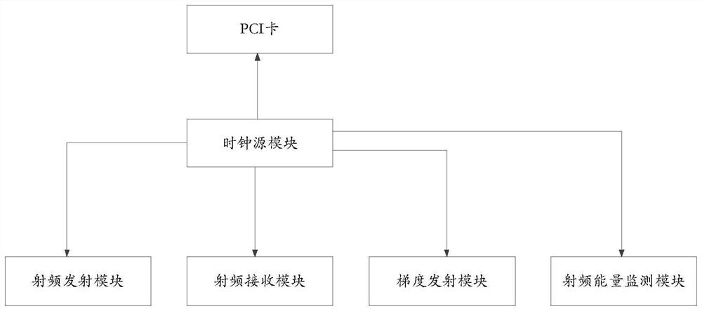
[0056] Embodiment 2: A magnetic resonance spectrometer system for realizing clock synchronization of the magnetic resonance spectrometer.

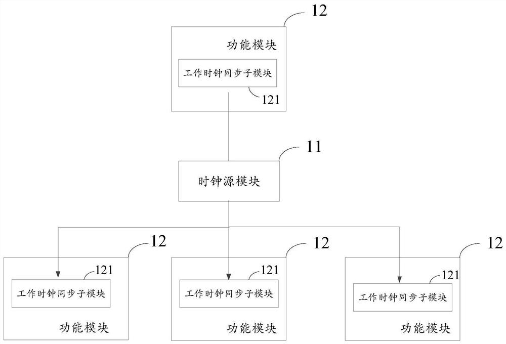
[0057] The system includes: a clock source module and a radio frequency link composed of a radio frequency transmitting module and a radio frequency receiving module; the clock source module is used to supply synchronous clock signals to the radio frequency transmitting module and the radio frequency receiving module respectively; the radio frequency transmitting module and the radio frequency receiving module The modules all include: a working clock synchronization sub-module, which is used to receive a synchronous clock signal, and obtain one or more working clock signals that are synchronous with the clock source module and have low clock jitter based on the synchronous clock signal.

[0058] Wherein, the frequency of the synchronous clock signal is 10MHz, the digital-to-analog conversion chip DAC conversion clock of the radio frequency tra


PUM


Abstract

The invention relates to a magnetic resonance spectrometer system for realizing clock synchronization of a magnetic resonance spectrometer. The system comprises a clock source module and one or more function modules connected with the clock source module; the clock source module is used for supplying a synchronous clock signal to each function module; and each function module comprises a work clock synchronization sub-module which is used for receiving a synchronous clock signal corresponding to the function module and acquiring one or more work clock signals which are synchronous with the clock source module and have low clock jitter based on the synchronous clock signal. The invention provides a package of solutions for the whole clock synchronization for the spectrometer system, the clock synchronization among the constituent units of the spectrometer system is realized, and the requirement that the constituent units of the spectrometer acquire the clock which is synchronous with the clock signal of the spectrometer clock source unit and has low jitter is met, so that a solid foundation is laid for a spectrometer system to serve magnetic resonance high-quality scanning imaging.

Description


Claims


Application Information

Patent Timeline
Owner 上海电气(集团)总公司智惠医疗装备分公司
Why Eureka
Try Eureka