Channel monitoring method, demodulation method, device, equipment and storage medium

A channel monitoring and channel technology, applied in transmission monitoring, electromagnetic wave transmission systems, electrical components, etc., can solve the problem of low channel performance accuracy, improve accuracy, avoid distortion, and avoid output results that are not enough to accurately reflect channel performance Effect

Pending Publication Date: 2021-12-10
THE HONG KONG POLYTECHNIC UNIV SHENZHEN RES INST
View PDF4 Cites 0 Cited by
  • Summary
  • Abstract
  • Description
  • Claims
  • Application Information

AI Technical Summary

Benefits of technology

This technology allows for accurate analysis by reducing noise interference caused during data transmission between different components within an electronic device's communication system. By applying this method on specific parts or channels that are already used with other devices connected through wires, it prevents any changes made over time affecting these connections. Overall, this improves overall quality control measures across multiple systems such as wireless networks and mobile phones.

Problems solved by technology

This patented technology solves issues with current methods where signals are collected from an analog device or converted into digital data before being processed on another chip due to limitations such as limited resolution at high frequencies caused by the physical properties of the devices themselves (such as impedance) which affects how well they work when dealing with higher-frequency waves. Additionally, this method requires expensive equipment like filters and amplifiers, making it difficult to achieve accurate results over longer distances without increasing costs associated therewith.

Method used


Image

  • Channel monitoring method, demodulation method, device, equipment and storage medium
  • Channel monitoring method, demodulation method, device, equipment and storage medium
  • Channel monitoring method, demodulation method, device, equipment and storage medium

Examples


Embodiment Construction

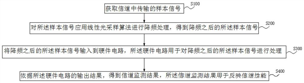
[0051] The technical solutions in the present invention are clearly and completely described below in conjunction with the embodiments and the accompanying drawings. Based on the embodiments of the present invention, all other embodiments obtained by persons of ordinary skill in the art without making creative efforts belong to the protection scope of the present invention.

[0052] After research, it is found that the performance of the channel can be obtained by collecting the signal transmitted in the channel and analyzing the transmitted signal. The frequency of the signal transmitted in the existing channel is relatively large, and the bandwidth of the hardware circuit used to process the signal is not enough to be suitable for processing the signal of a relatively large frequency, that is, the frequency of the signal does not match the bandwidth of the hardware circuit used to process the signal. The processing of the signal by the hardware circuit is affected, so that the


PUM


Abstract

The invention relates to the technical field of channel monitoring, in particular to a channel monitoring method, a demodulation method, device, equipment and a storage medium. According to the invention, a sample signal transmitted in a channel is collected, frequency reduction processing is carried out on the sample signal by applying a linear optical sampling algorithm, the sample signal after frequency reduction is input into a hardware circuit, and the hardware circuit processes the sample signal after frequency reduction to obtain an output result for the sample signal after frequency reduction, and the performance of the channel can be obtained according to the output result. According to the invention, frequency reduction is carried out on the sample signal firstly, so that the sample signal after frequency reduction is matched with the bandwidth of the hardware circuit, thereby avoiding distortion of the sample signal caused by mismatching of the bandwidth of the hardware circuit and the frequency of the sample signal, and improving the accuracy of the obtained channel performance.

Description


Claims


Application Information

Patent Timeline
Owner THE HONG KONG POLYTECHNIC UNIV SHENZHEN RES INST
Why Eureka
Try Eureka