Magnetoelectric dipole broadband polarization torsion lens antenna and phase compensation method thereof

A lens antenna and broadband polarization technology, which is applied in the directions of individually powered antenna arrays, antennas, and antenna arrays, can solve problems such as narrow bandwidth, achieve low cost, facilitate expansion into arrays, and facilitate mass production.

Pending Publication Date: 2021-12-28
SOUTHEAST UNIV
View PDF0 Cites 0 Cited by
  • Summary
  • Abstract
  • Description
  • Claims
  • Application Information

AI Technical Summary

Benefits of technology

This new type of radio wave device called LCAR (Liquid Crystal Antennas) has been developed that allows for better signal reception compared with traditional linear arrays used today. It achieves this through its unique design which includes multiple small circles or rectangular areas arranged around each other instead of just one square area. These tiny radar reflectors are designed to be very thin and have high efficiency at microwave frequencies. They also work well even when transmitting signals without being obstructed from viewing them effectively due to their specific shape. Overall, these technical features make LC AR technology more efficient than current devices while still providing improved performance.

Problems solved by technology

This patented technical problem addressed by this patents relates to improving transmitting elements used in communication devices like laser diodes (LDs) or optic fibers that produce circularlypolarized waves without losing its effectiveness when emitted from an external source at different angles relative to each other.

Method used


Image

  • Magnetoelectric dipole broadband polarization torsion lens antenna and phase compensation method thereof
  • Magnetoelectric dipole broadband polarization torsion lens antenna and phase compensation method thereof
  • Magnetoelectric dipole broadband polarization torsion lens antenna and phase compensation method thereof

Examples


Embodiment 1

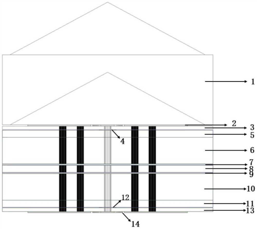
[0041] see Figure 1-Figure 5 , the present embodiment provides a magnetoelectric dipole broadband polarization twisted lens antenna, which includes a plurality of antenna elements, wherein each antenna element includes a tapered dielectric coating layer 1, a top metal Layer 2, first dielectric layer 3, second metal layer 4, first adhesive layer 5, second dielectric layer 6, third metal layer 7, second adhesive layer 8, fourth metal layer 9, third dielectric Layer 10, third adhesive layer 11, fifth metal layer 12, fourth dielectric layer 13 and bottom metal layer 1.

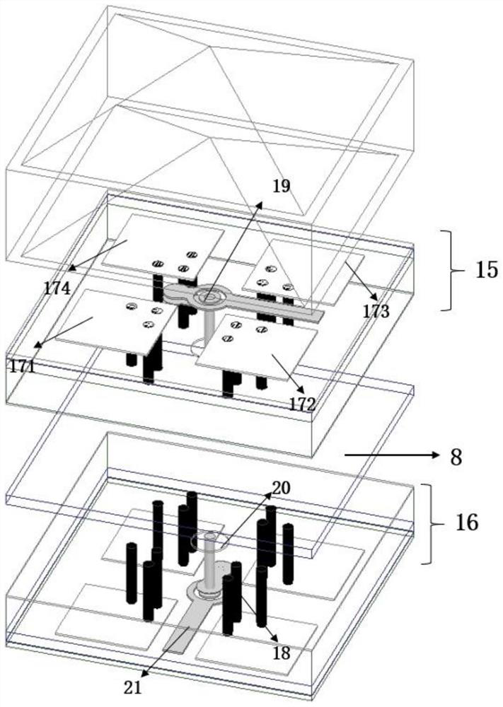
[0042] The top metal layer 2, the first dielectric layer 3, the second metal layer 4, the first adhesive layer 5, the second dielectric layer 6, the third metal layer 7, and the electric dipole arranged on the surface of the top metal layer 2, And the magnetic dipole 18 provided inside the transmitting antenna 15 constitutes the transmitting antenna 15 of the lens antenna unit.

[0043] The fourth metal layer 9, t

Embodiment 2

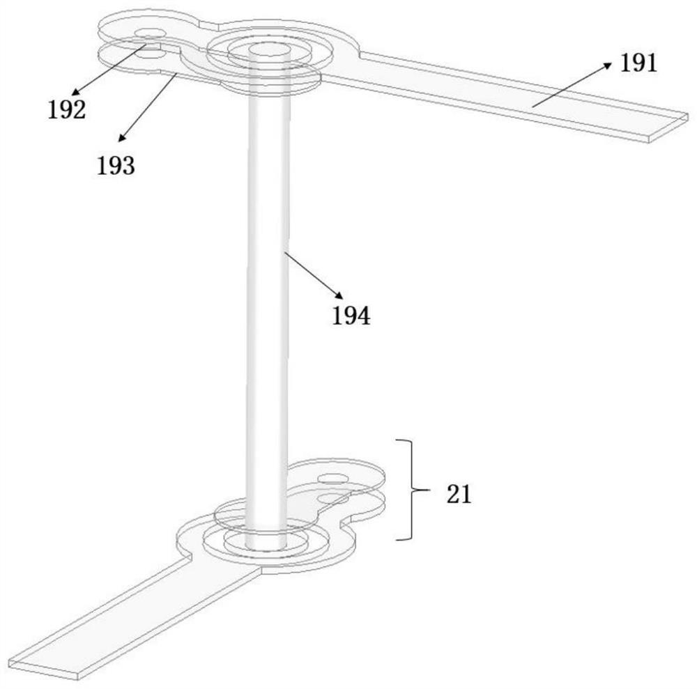
[0055] see Figure 6-Figure 12 , this embodiment provides a phase compensation method for a magnetoelectric dipole broadband polarization twisted lens antenna. In this embodiment, in order to realize the conversion from linear polarization to circular polarization, the center feed of transmitting antenna 15 The probe of the structure 19 can be rotated at intervals of 90°, thereby generating circularly polarized transmitting beams, while the receiving antenna 16 and the tapered dielectric coating layer 1 cooperate with each other to achieve the effect of phase compensation.

[0056] Specifically, in this embodiment, this patent proposes and compares and analyzes four phase compensation schemes, which are 1-bit, 2-bit, super 2-bit and full-phase adjustment phase compensation schemes, wherein, in 1-bit phase compensation The above-mentioned tapered dielectric coating layer 1 is not used in the scheme, and the other three phase compensation schemes use the rotation of the feeding pro


PUM

PropertyMeasurementUnit
Thicknessaaaaaaaaaa
Thicknessaaaaaaaaaa
Thicknessaaaaaaaaaa

Abstract

The invention discloses a magnetoelectric dipole broadband polarization torsion lens antenna and a phase compensation method thereof. The lens antenna comprises a transmitting antenna and a receiving antenna, wherein the transmitting antenna is composed of a top metal layer, a first dielectric layer, a second metal layer, a first bonding layer, a second dielectric layer and a third metal layer, and the receiving antenna is composed of a fourth metal layer, a third dielectric layer, a third bonding layer, a fifth metal layer, a fourth dielectric layer and a bottom metal layer. A conical medium coating layer is arranged at the upper end of the transmitting antenna and is mainly used for increasing the phase adjusting range; the surface of the top metal layer is provided with an electric dipole, and a magnetic dipole and a central feed structure are also arranged. The conversion from linear polarized waves to circularly polarized waves is flexibly realized by adopting a sequential rotation scheme on a transmitting antenna layer, and a super 2-bit phase compensation scheme is specifically provided, so that relatively wide 3-dB gain and AR overlapping bandwidth (47%) are realized, and only sub-wavelength profile height is realized.

Description


Claims


Application Information

Patent Timeline
Owner SOUTHEAST UNIV
Why Eureka
Try Eureka