Dirt collecting tank and cleaning equipment

A sewage collecting box and box body technology, which is used in cleaning equipment, cleaning machinery, cleaning devices, etc., can solve the problems of low separation efficiency of the sewage collecting box, improve separation efficiency, reduce solid and liquid dirt content, and reduce replacement. effect of times

Pending Publication Date: 2022-02-25
GREE ELECTRIC APPLIANCES INC OF ZHUHAI
View PDF0 Cites 0 Cited by
  • Summary
  • Abstract
  • Description
  • Claims
  • Application Information

AI Technical Summary

Problems solved by technology

[0003] This application aims at the problem of low separation efficiency of the dirt collection box of cleaning equipment in the prior art, and proposes a dirt collection box and cleaning equipment, which have the technical effect of high separation effect and good cleaning effect

Method used


Image

  • Dirt collecting tank and cleaning equipment
  • Dirt collecting tank and cleaning equipment
  • Dirt collecting tank and cleaning equipment

Examples


Example Embodiment

[0029] In order to make the above objects, features, and advantages of the present application, the specific embodiments of the present application will be described in detail below with reference to the accompanying drawings. Many specific details are set forth in the following description to fully understand the present application. However, the present application can be implemented in many other fails there are many otherwise described herein, and those skilled in the art can make similar improvements without departing from the connotation of the present application, so the present application is not limited by the specific embodiments disclosed in the following.

[0030] In the description of this application, it is to be understood that the terms "center", "longitudinal", "horizontal", "length", "width", "thickness", "upper", "under", "front", " After "," left "," right "," vertical "," horizontal "," top "," bottom "," internal "," outside "," clockwise "," counterclock "," ax


PUM


Abstract

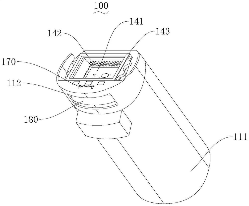
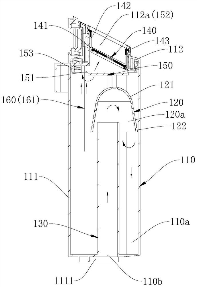
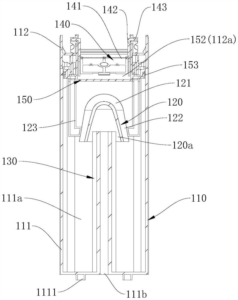
The invention relates to a dirt collecting tank and cleaning equipment. The dirt collecting tank comprises a box body, a first baffle, an air inlet duct and a filtering assembly. The box body is provided with a containing cavity, and an air inlet and an air outlet which are communicated with the containing cavity, and the air outlet is located in the upper side of the box body. The first baffle is arranged in the containing cavity and located below the air outlet, a separation cavity with an opening in one side is defined by the first baffle, and the opening faces downwards. The air inlet duct is arranged in the containing cavity, one end of the air inlet duct is connected to the air inlet, and the other end of the air inlet duct extends into the separation cavity through the opening. The filtering assembly is arranged at the air outlet and used for only allowing air flowing through the air outlet to pass through. Compared with the prior art, most solid-liquid dirt stays in the containing cavity when entering the air outlet through the first baffle, so that the content of the solid-liquid dirt remaining on the filtering assembly is remarkably reduced, the separation efficiency of the filtering assembly is remarkably improved, meanwhile, the replacement frequency of the filtering assembly is also reduced, and the cleaning effect of the cleaning equipment can be improved.

Description


Claims


Application Information

Patent Timeline
Owner GREE ELECTRIC APPLIANCES INC OF ZHUHAI
Why Eureka
Try Eureka