Low-voltage switch cabinet for shock absorption and dust prevention

A low-voltage switchgear and dust-proof technology, which is applied in the field of low-voltage switchgear, can solve the problems of affecting the heat dissipation effect of the cooling device, affecting the air flow, and consuming manpower and material resources, so as to save manpower and material resources, reduce vibration, and improve cleaning effect.

Pending Publication Date: 2022-06-17
邹锡锋
View PDF0 Cites 0 Cited by
  • Summary
  • Abstract
  • Description
  • Claims
  • Application Information

AI Technical Summary

Problems solved by technology

[0004] When the traditional low-voltage switchgear is used for a long time, especially the switchgear used for traffic lights and street lights on the side of the road, its internal equipment is prone to generate a lot of heat, so a heat dissipation device is needed to discharge the internal heat. To reduce the damage of roadside dust to the internal equipment of the switchgear, it is necessary to install a filter screen, but as time goes by, a large amount of dust will accumulate on the filter screen of the heat sink, which will seriously affect the flow of air flow, thereby affecting the heat dissipation effect of

Method used


Image

  • Low-voltage switch cabinet for shock absorption and dust prevention
  • Low-voltage switch cabinet for shock absorption and dust prevention
  • Low-voltage switch cabinet for shock absorption and dust prevention

Examples


Example Embodiment

[0036]下面将结合本发明实施例中的附图,对本发明实施例中的技术方案进行清楚、完整地描述;显然,所描述的实施例仅仅是本发明一部分实施例,而不是全部的实施例,基于本发明中的实施例,本领域普通技术人员在没有做出创造性劳动前提下所获得的所有其他实施例,都属于本发明保护的范围。

[0037]在本发明的描述中,需要说明的是,术语“上”、“下”、“内”、“外”、“顶 / 底端”等指示的方位或位置关系为基于附图所示的方位或位置关系,仅是为了便于描述本发明和简化描述,而不是指示或暗示所指的装置或元件必须具有特定的方位、以特定的方位构造和操作,因此不能理解为对本发明的限制。此外,术语“第一”、“第二”仅用于描述目的,而不能理解为指示或暗示相对重要性。

[0038]在本发明的描述中,需要说明的是,除非另有明确的规定和限定,术语“安装”、“设置有”、“套设 / 接”、“连接”等,应做广义理解,例如“连接”,可以是固定连接,也可以是可拆卸连接,或一体地连接;可以是机械连接,也可以是电连接;可以是直接相连,也可以通过中间媒介间接相连,可以是两个元件内部的连通。对于本领域的普通技术人员而言,可以具体情况理解上述术语在本发明中的具体含义。

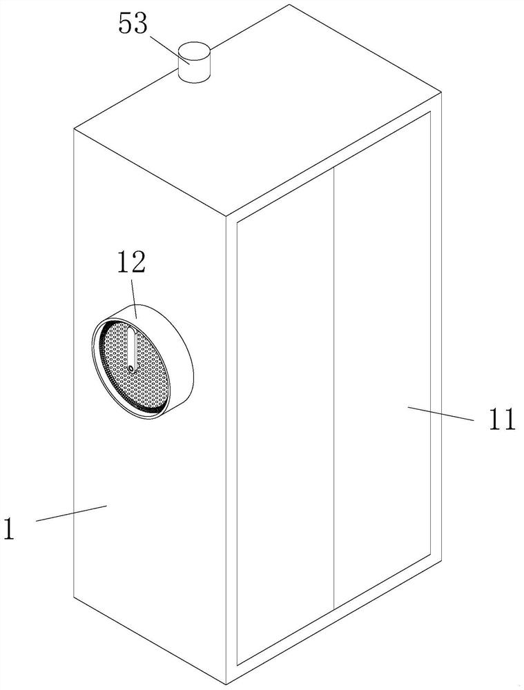
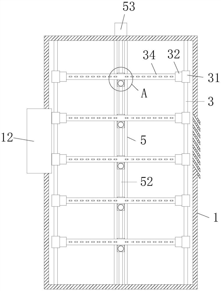
[0039]如图1、图4与图5所示,本发明实施例提供一种用于减震防尘的低压开关柜,包括柜体1,所述柜体1的前端面铰接有开合门11,所述柜体1的左端面靠近中间的位置嵌入式固定连接有撑管12,所述撑管12的内表面靠近左侧的位置固定连接有滤网13,所述撑管12的内表面靠近右侧的位置通过连接架固定连接有电机一14,所述电机一14的输出轴外表面靠近滤网13右侧的位置固定连接有扇叶15,所述柜体1的右端面开设有散热槽,所述滤网13的左侧设置有清理机构2。

[0040]通过采用上述技术方案,工作时,当柜体1内部温度较高时,控制电机一14逆时针转动,通过输出轴带动扇叶15逆时针转动,从而能够将外界空气吸入柜体1内部,与其内部空气进行换热,随之从柜体1右侧散热槽排出,能够有效的将柜体1内部的热量带走,保证了柜体1内部设备的正常工作,通过设置有滤网13能够减小灰尘进入柜体1内部对其内部设备造成损害,当滤网13外表面积附大量灰尘时,只需控制清理机构2工作,即可将其外表面灰尘清理干净,保证了气流的正常流通。

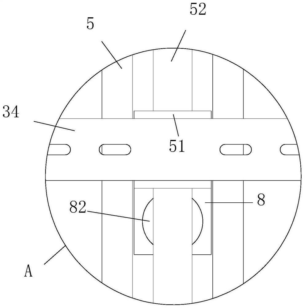
[0041]作为本发明的一种实施例,如图4与图5所示,所述清理机构2包括轴承一21、


PUM


Abstract

The invention discloses a low-voltage switch cabinet for shock absorption and dust prevention, and belongs to the technical field of power equipment.The low-voltage switch cabinet for shock absorption and dust prevention comprises a cabinet body, an opening and closing door is hinged to the front end face of the cabinet body, and a supporting pipe is fixedly connected to the position, close to the middle, of the left end face of the cabinet body in an embedded mode; a filter screen is fixedly connected to the position, close to the left side, of the inner surface of the supporting pipe, a first motor is fixedly connected to the position, close to the right side, of the inner surface of the supporting pipe through a connecting frame, and fan blades are fixedly connected to the position, close to the right side of the filter screen, of the outer surface of an output shaft of the first motor. The cleaning effect is better, the distance between the adjacent fixing plates can be adjusted more conveniently, equipment of different sizes and types can be installed and fixed conveniently, a large amount of manpower and material resources are saved, and meanwhile damage to the equipment in the cabinet body caused by vibration of the cabinet body can be greatly relieved.

Description


Claims


Application Information

Patent Timeline
Owner 邹锡锋
Why Eureka
Try Eureka