Power plant thermal instrument dust removal device

A technology for thermal instruments and dust removal devices, which is applied in chemical instruments and methods, cleaning methods and utensils, and cleaning methods using gas flow, etc. and other problems, to achieve good cleaning and improve the effect of cleaning

Pending Publication Date: 2022-08-05
SHENHUA ZHUNGER ENERGY
View PDF0 Cites 0 Cited by
  • Summary
  • Abstract
  • Description
  • Claims
  • Application Information

AI Technical Summary

Problems solved by technology

[0003] Thermal instruments in power plants are prone to accumulate a large amount of dust and foreign matter during long-term use. Failure to clean them regularly will cause damage to the instrument, resulting in inaccurate readings and affecting the product qualification rate. Moreover, the routine cleaning of the sprinkler type is easy to cause certain damage to the precision parts of the instrument. And for some

Method used


Image

  • Power plant thermal instrument dust removal device
  • Power plant thermal instrument dust removal device
  • Power plant thermal instrument dust removal device

Examples


Example Embodiment

[0034] The specific embodiments of the present application will be further described below with reference to the accompanying drawings.

[0035] It is easy to understand that, according to the technical solutions of the present application, without changing the essential spirit of the present application, those of ordinary skill in the art can interchange various structural modes and implementation modes. Therefore, the following specific embodiments and accompanying drawings are only exemplary descriptions of the technical solutions of the present application, and should not be regarded as the whole of the present application or as limitations or restrictions on the technical solutions of the application.

[0036] Orientation terms such as up, down, left, right, front, rear, front, back, top, bottom, etc. mentioned or possibly mentioned in this specification are defined relative to the configurations shown in the respective drawings, which are It is a relative concept, so it may


PUM


Abstract

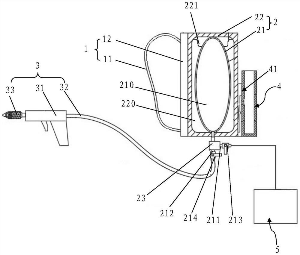
The invention discloses a power plant thermal instrument dust removal device which comprises a moving mechanism, a gas storage mechanism and a gas blowing mechanism, the gas storage mechanism is arranged in the moving mechanism, the gas storage mechanism comprises a gas charging port used for charging high-pressure gas and a gas outlet used for outputting gas, and the gas blowing mechanism is connected with the gas outlet; the air blowing mechanism comprises a dust blowing gun and a flexible pipe, one end of the flexible pipe is connected with the air outlet, the other end of the flexible pipe is connected with the dust blowing gun, and the dust blowing gun is used for blowing air outwards. The device is good in cleaning effect and convenient to operate.

Description


Claims


Application Information

Patent Timeline
Owner SHENHUA ZHUNGER ENERGY
Why Eureka
Try Eureka