Spraying device for electric power grid outdoor equipment processing and spraying process thereof
A technology for outdoor equipment and spraying equipment, applied in spraying equipment, spray booths, cleaning methods and utensils, etc., can solve problems such as increased work risk, unclean dust, poor spraying effect, etc., to improve quality and solve fixed spraying angle , Solve the effect of low spraying efficiency
- Summary
- Abstract
- Description
- Claims
- Application Information
AI Technical Summary
Problems solved by technology
Method used
Image


Examples
Example Embodiment
[0050] Example 1:
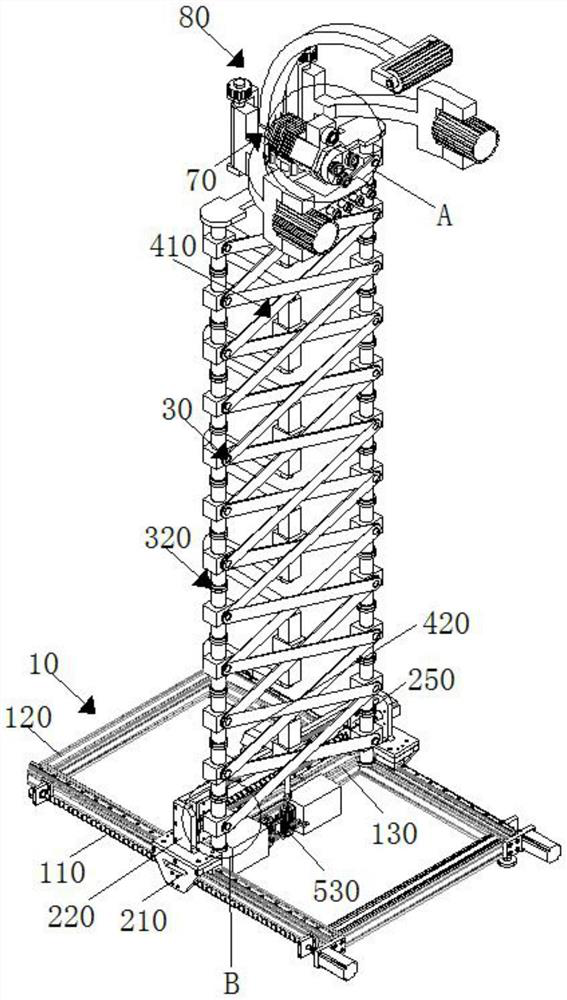
[0051] Such as figure 1 , figure 2 , image 3 , Figure 4 , Figure 5 , Image 6 , Figure 7 and Figure 8 As shown, the present embodiment proposes a spraying device for processing a power grid outdoor equipment, including positioning base 10, further comprising,
[0052] The distance adjustment assembly 20 is mounted on the positioning base 10 and linearly moves along the positioning base 10;
[0053] The scissor link group 30, the end hinge point of the shear link group 30 is rotated connected to the positioning block 310, and the top portion of the positioning block 310 is provided with a symmetric distribution positioning portion 320, and the bottom of the scissor link group 30 The end is mounted at the adjustment end of the distance adjustment assembly through the positioning block 310, and the positioning block 330 is mounted at the central hinge point of the scissors set 30;
[0054] The plow assembly 40 is mounted on the distance adjustment assembly 30, and the
Example Embodiment
[0065] Example 2:
[0066] Next, in conjunction with specific mode of operation, further introduction of the scheme in Example 1 is shown in detail below.
[0067] Such as figure 1 , figure 2 , image 3 , Figure 4 , Figure 5 , Image 6 , Figure 7 , Figure 8 , Figure 9 and Figure 10 As shown, the present embodiment proposes a spraying device for processing a power grid outdoor equipment, including positioning base 10, further comprising,
[0068] The distance adjustment assembly 20 is mounted on the positioning base 10 and linearly moves along the positioning base 10;
[0069] The scissor link group 30, the end hinge point of the shear link group 30 is rotated connected to the positioning block 310, and the top portion of the positioning block 310 is provided with a symmetric distribution positioning portion 320, and the bottom of the scissor link group 30 The end is mounted at the adjustment end of the distance adjustment assembly through the positioning block 310, and the positioning
Example Embodiment
[0081] Example 3:
[0082] Next, in connection with the specific mode of operation, the schemes in Examples 1 and Example 2 are described below, as described below with reference to the description: The positioning unit 320 includes a positioning post 321 mounted on top of the positioning block 310 and the bottom portion and a column mounted at the positioning post 321. In the end of the magazine portion 322, the adjacent link portion 322 is contracted with each other, and the stability of the shear link group 30 in the storage transport state is improved.
PUM
 Abstract
Description
Claims
Application Information
 - R&D Engineer
- R&D Manager
- IP Professional
- Industry Leading Data Capabilities
- Powerful AI technology
- Patent DNA Extraction
Browse by: Latest US Patents, China's latest patents, Technical Efficacy Thesaurus, Application Domain, Technology Topic.
© 2024 PatSnap. All rights reserved.Legal|Privacy policy|Modern Slavery Act Transparency Statement|Sitemap