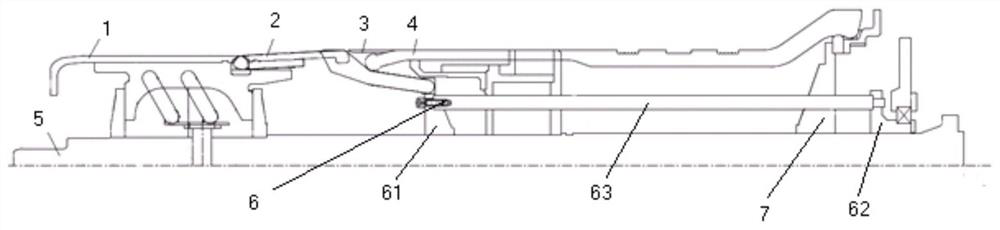
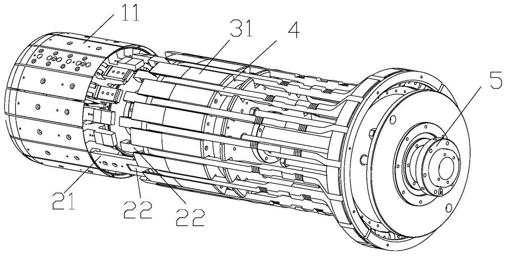
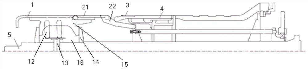
Molding drum

A technology of forming drum and spindle, applied in tires, other household appliances, household appliances, etc., can solve the problems of poor production efficiency of forming drum, and achieve the effect of ensuring quality and improving production efficiency

Pending Publication Date: 2022-03-01
MESNAC +1
View PDF0 Cites 0 Cited by
  • Summary
  • Abstract
  • Description
  • Claims
  • Application Information

AI Technical Summary

Problems solved by technology

[0004] The main purpose of the present invention is to provide a forming drum to

Method used


Image

  • Molding drum
  • Molding drum
  • Molding drum

Examples


Embodiment Construction

[0029] It should be noted that, in the case of no conflict, the embodiments in the present application and the features in the embodiments can be combined with each other. The present invention will be described in detail below with reference to the accompanying drawings and examples.

[0030] As recorded in the background technology, in the existing air spring forming equipment, the drum used in the secondary process is mainly used, and the realization of most functions requires manual assistance. The drum used in the secondary process needs to position the large and small steel rings separately, so it is easy to cause deformation of the embryo and affect the quality of the air spring, and most of the actions in the secondary process need to be completed manually, resulting in low production efficiency and poor product quality. The secondary forming process has low lamination precision, low degree of automation, and excessive manual intervention, which seriously affects the form


PUM


Abstract

The invention provides an assembly drum which comprises a plurality of anti-package rods, and the first end of each anti-package rod is provided with an anti-package position located above a flat drum and an initial position located between a guide section and a first driving seat; and the second driving seat is movably arranged on the main shaft in a sleeving mode, the second end of the reverse wrapping rod is connected to the second driving seat in a pivoted mode, and the second driving seat moves in the axial direction of the main shaft. When the forming drum works, the expansion and contraction of the flat drum can be realized through the movement of the driving shaft, the tilting and recovery of the guide rod can be realized through the movement of the first driving seat, and the turn-up action of the turn-up rod can be completed through the matched movement of the second driving seat and the first driving seat, so that the turn-up of a steel ring by a material can be realized, the first driving seat, the second driving seat and the driving shaft can be controlled by adopting a servo motor, so that the gluing of a rubber material and the turn-up of a steel ring can be completed on one drum, the production efficiency is greatly improved, and the quality of an air spring is ensured.

Description


Claims


Application Information

Patent Timeline
Owner MESNAC
Why Eureka
Try Eureka