Embedded positioning device for constructional engineering

A positioning device and construction engineering technology, applied in construction, supporting device, drilling equipment and methods, etc., can solve the problems of affecting construction progress, inaccurate positioning, large measurement error, etc., and achieve the effect of convenient positioning and use

Pending Publication Date: 2022-03-11
CHINA CONSTR FIFTH ENG DIV CORP LTD
View PDF8 Cites 0 Cited by
  • Summary
  • Abstract
  • Description
  • Claims
  • Application Information

AI Technical Summary

Benefits of technology

This patented technical features include an improved protection covering system where movable covers may also have guided rollers attached thereto. These guide roller systems allow for precise placement when needed without requiring excessive force and provide better safety than traditional methods such as manually operated ladders. Additionally, there exist various devices called position fixing tools (PTM) placed along the edges of these screens to improve their precision and ease-of-positioning. Overall, this innovation simplifies the construction and operation processes of the protected area's location control shield.

Problems solved by technology

The technical problem addressed by this patented technology relates how accurate placement and alignment can occur during embedding part installations due to manual methods being performed with traditional tools like calipers and chalk markers. This results in increased costs associated with laborious tasks and potential delays caused by incorrect placements between different types of material found within these workpieces.

Method used


Image

  • Embedded positioning device for constructional engineering
  • Embedded positioning device for constructional engineering
  • Embedded positioning device for constructional engineering

Examples


Embodiment 1

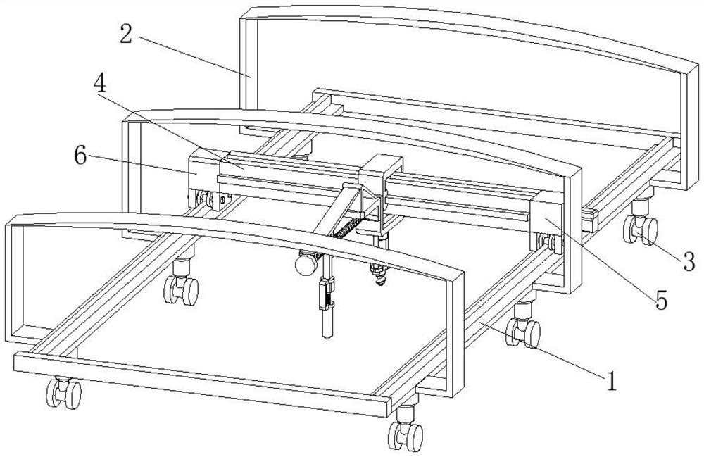
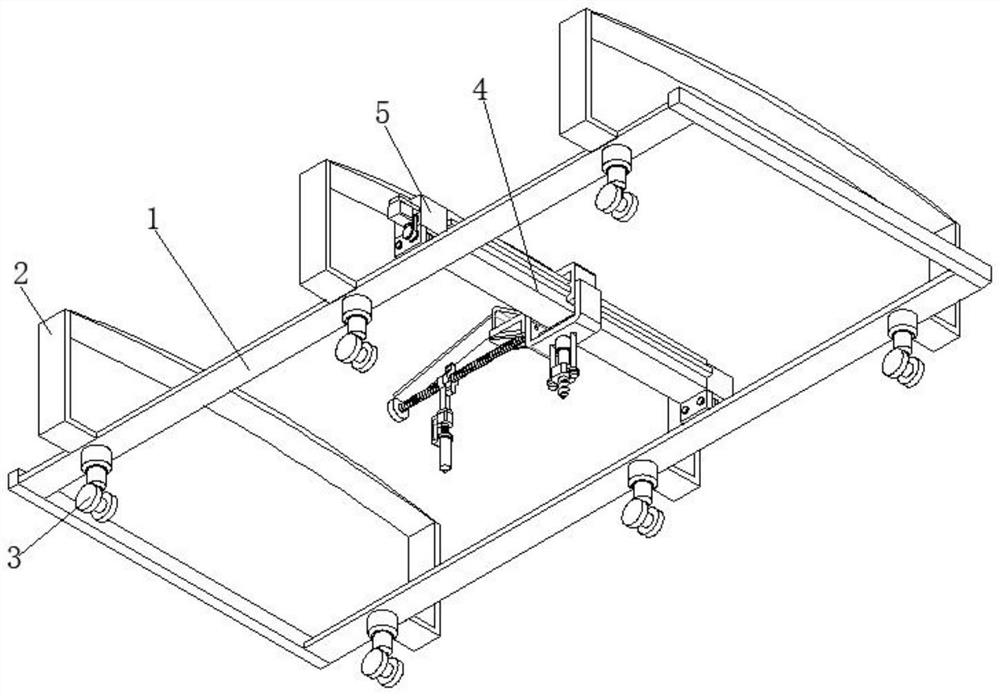
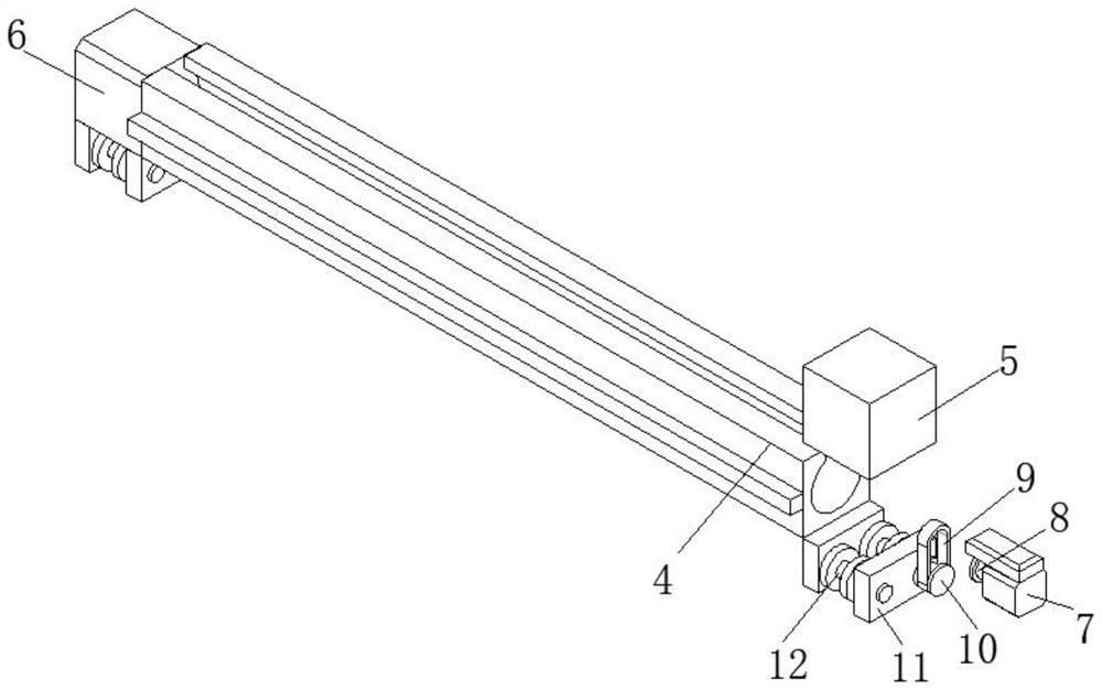
[0034] see Figure 1-8 , the present invention provides a technical solution: a pre-embedded positioning device for construction projects, including a mobile protective cover 4, the two sides of the mobile protective cover 4 are provided with a fixed block 5 and a motor cover 6, the fixed block 5 and the motor cover The bottom ends of 6 are symmetrically and fixedly connected with a fixed side plate 11 , and the opposite inner side of the fixed side plate 11 is rotatably connected with a moving pulley 12 , and one end of the moving pulley 12 is fixedly connected with a driven pulley 10 , The driven pulley 10 passes through the transmission belt 9 . Drive connection with the driving pulley 8, one end of the driving pulley 8 is provided with a first motor 7, the driving pulley 8 is fixedly connected to the driving end of the first motor 7, the driving pulley 8 is rotatably connected to one side of the fixed block 5, the first motor 7 It is fixedly connected to one side of the fixed

Embodiment 2

[0037] see Figure 1-8 , the present invention provides a technical solution: a pre-embedded positioning device for construction projects, including a mobile protective cover 4, the two sides of the mobile protective cover 4 are provided with a fixed block 5 and a motor cover 6, the fixed block 5 and the motor cover The bottom ends of 6 are symmetrically and fixedly connected with a fixed side plate 11 , and the opposite inner side of the fixed side plate 11 is rotatably connected with a moving pulley 12 , and one end of the moving pulley 12 is fixedly connected with a driven pulley 10 , The driven pulley 10 passes through the transmission belt 9 . Drive connection with the driving pulley 8, one end of the driving pulley 8 is provided with a first motor 7, the driving pulley 8 is fixedly connected to the driving end of the first motor 7, the driving pulley 8 is rotatably connected to one side of the fixed block 5, the first motor 7 It is fixedly connected to one side of the fixed


PUM


Abstract

The invention discloses an embedded positioning device for constructional engineering, which comprises a movable protective cover, two sides of the movable protective cover are provided with a fixed block and a motor cover, and the bottom ends of the fixed block and the motor cover are symmetrically and fixedly connected with fixed side plates; a fixed block and a motor cover are arranged on the two sides of the movable protective cover, fixed side plates are symmetrically and fixedly connected to the bottom ends of the fixed block and the motor cover, movable wheels are rotationally connected to the opposite positions of the fixed side plates, and a driven belt pulley is fixedly connected to one end of the movable wheel arranged below the fixed block; the driven belt pulley is in transmission connection with a driving belt pulley through a transmission belt, and the driving belt pulley is fixedly connected to the driving end of a first motor, so that when the first motor is started, the driving end of the first motor drives the driving belt pulley to rotate, the movable protective cover moves at the top end of the sliding rail frame, and the position of the movable protective cover can be adjusted; and positioning use is facilitated.

Description


Claims


Application Information

Patent Timeline
Owner CHINA CONSTR FIFTH ENG DIV CORP LTD
Why Eureka
Try Eureka