Water gate downstream energy dissipation device for water conservancy project

A water conservancy project and energy dissipation device technology, which is applied in water conservancy projects, sea area projects, coastline protection, etc., can solve the problems of water flow reduction, damage, foundation deformation, etc., and achieve the effects of energy dissipation, impact mitigation and damage reduction

Pending Publication Date: 2022-04-05
李永强
View PDF0 Cites 0 Cited by
  • Summary
  • Abstract
  • Description
  • Claims
  • Application Information

AI Technical Summary

Problems solved by technology

[0002] When the sluice is opened, the water flow in front of the sluice will discharge at a high speed and have a large kinetic energy, which will cause severe erosion of the downstream apron and sea diffuser, resulting in damage. In the river, with the strong impact of the water flow, it will cause the downstream If the part is damaged, a stilling pool is generally installed downstream to dissipate energy, but the stilling pool is generally composed of multiple layers, which strengthens the ability to resist impact, but does not prevent the impact of water flow. In this way, after a long period of scouring, it will affect the downstream part of the river, and there may be deformation and subsidence of the foundation. The strong impact of the water flow is mainly due to the blocking of the gate, where the water level is high and the water level is low. In this process, it would be better if the flow direction of the water flow can be changed. Therefore, the inventor invented and created a downstream energy dissipation device of the sluice in water conservancy projects to solve the problem of energy dissipation downstream of the sluice.

Method used


Image

  • Water gate downstream energy dissipation device for water conservancy project
  • Water gate downstream energy dissipation device for water conservancy project
  • Water gate downstream energy dissipation device for water conservancy project

Examples


Example Embodiment

[0018] The technical solutions in the embodiments of the present invention will be clearly and completely described below with reference to the accompanying drawings in the embodiments of the present invention. Obviously, the described embodiments are only a part of the embodiments of the present invention, but not all of the embodiments. Based on the embodiments of the present invention, all other embodiments obtained by those of ordinary skill in the art without creative efforts shall fall within the protection scope of the present invention.

[0019] see Figure 1-3 , the present invention provides a kind of technical scheme:

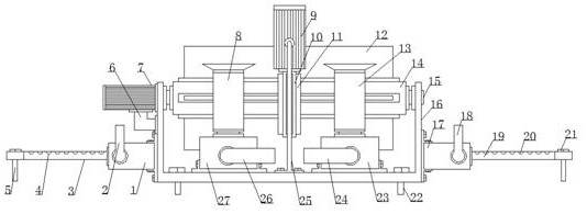
[0020] An energy dissipation device downstream of a sluice in a water conservancy project, comprising a support frame 16, the bottom surface of the support frame 16 is symmetrically equipped with fastening screws 22, the right side of the support frame 16 is fixedly installed with a second water pump 17, the second water pump The water inlet end of 17


PUM


Abstract

The water gate downstream energy dissipation device for the water conservancy project comprises a supporting frame, fastening screws are symmetrically installed on the bottom face of the supporting frame, a second water pump is fixedly installed on the right side of the supporting frame, and the water inlet end of the second water pump is connected with a third connecting pipe. A fourth connecting pipe is connected to the water outlet end of the second water pump, second through holes are evenly formed in the upper surface of the fourth connecting pipe, a second screw rod is installed at the outer end of the fourth connecting pipe, a first water pump is fixedly installed on the lower side of the left side face of the supporting frame, and a first connecting pipe is connected to the water inlet end of the first water pump; the water outlet end of the first water pump is connected with a second connecting pipe, first through holes are evenly formed in the upper surface of the second connecting pipe, and a first screw rod is installed at the outer end of the second connecting pipe. The multiple water pumps are ingeniously used for providing power, the water flow direction of the downstream of the river channel is controlled, and energy dissipation of the downstream of the water gate is effectively achieved.

Description


Claims


Application Information

Patent Timeline
Owner 李永强
Why Eureka
Try Eureka