Tunnel deformation real-time monitoring system and monitoring method

A real-time monitoring system and real-time monitoring technology, applied in the direction of electric/magnetic solid deformation measurement, measuring instruments, measuring devices, etc., can solve the problems of high measurement cost, high price, and failure to obtain early warning information, and achieve high precision and accuracy , easy erection and low cost

Pending Publication Date: 2022-04-12
CIENET TECH BEIJING
View PDF1 Cites 0 Cited by
  • Summary
  • Abstract
  • Description
  • Claims
  • Application Information

AI Technical Summary

Benefits of technology

The present in this patented technology provides an improved way for detecting changes during tunneling operations without interrupting their progress or requiring expensive maintenance staffs. It uses arches that are placed on both sides of the tunnel walls with sensors attached at different locations along its length. This allows them to monitor these conditions accurately while also being affordable compared to traditional methods like manual observation techniques.

Problems solved by technology

Technically speaking, current methods involve analyzing or processing radio waves from different directions during tunneling operations to detect changes over time related to structural issues such as soil movement and stress crackings. These techniques require frequent manual checks and may only provide limited results if there were any significant deviations between expected values. Additionally, these existing systems rely heavily upon sensors like laser scanners (LS) to accurately determine the shape change induced by forces applied through the tunnel' s base material.

Method used


Image

  • Tunnel deformation real-time monitoring system and monitoring method
  • Tunnel deformation real-time monitoring system and monitoring method
  • Tunnel deformation real-time monitoring system and monitoring method

Examples


Embodiment Construction

[0036] The technical content of the present invention will be described in detail below in conjunction with the accompanying drawings and specific embodiments.

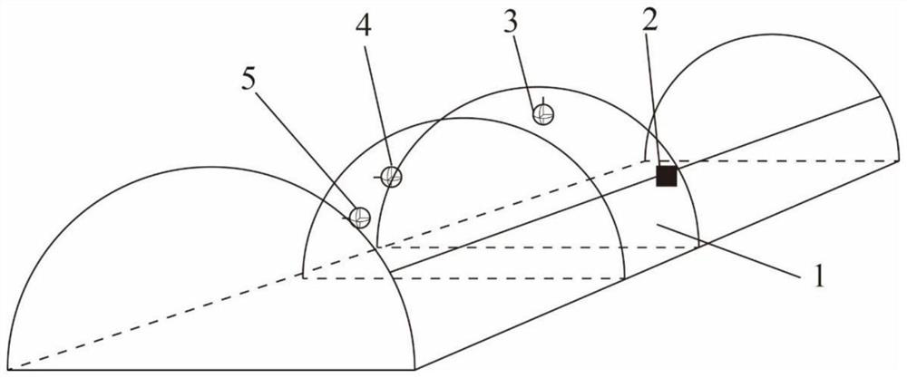
[0037] Such as figure 1 As shown, the embodiment of the present invention firstly provides a tunnel deformation real-time monitoring system, including a deformation monitoring module, a data transmission module, a data analysis module and an alarm module. The deformation monitoring module is connected to the data analysis module through the data transmission module, and the data analysis module analyzes and processes the monitoring data from the deformation monitoring module, and sends an alarm command to the alarm module or sends a monitoring command to the deformation monitoring module.

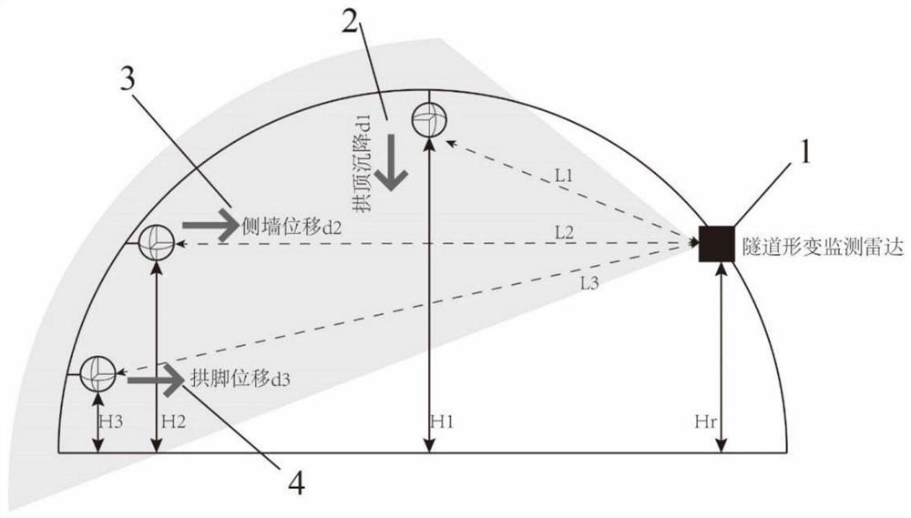
[0038] Such as figure 2 As shown, in the tunnel deformation real-time monitoring system provided by the present invention, the deformation monitoring module includes a plurality of monitoring units, each monitoring unit is erected o


PUM


Abstract

The invention discloses a tunnel deformation real-time monitoring system and monitoring method. The system comprises a deformation monitoring module, a data transmission module, a data analysis module and an alarm module, the deformation monitoring module comprises a plurality of monitoring units, each monitoring unit is erected on a cross section of a tunnel, the adjacent monitoring units are spaced by a preset distance, and each monitoring unit comprises a radar, a vault beacon, a side wall beacon and an arch foot beacon; wherein the radar is located at the position, away from the ground by a preset height, on the side wall of the tunnel; the vault beacon is positioned right above the vault of the tunnel; the side wall beacon is located on the other side wall of the tunnel; the arch springing beacons are located below the side wall beacons and are close to the arch springing of the tunnel; the vault beacons, the side wall beacons and the arch foot beacons are all-directional beacons. The tunnel deformation quantity can be monitored in real time under the condition that construction continuity is not affected.

Description


Claims


Application Information

Patent Timeline
Owner CIENET TECH BEIJING
Why Eureka
Try Eureka