Wet coal sample mixing rotary division machine

A shrinking machine and sample mixing technology, applied in the preparation of test samples, etc., can solve problems such as inability to divide materials evenly, inconvenient transportation, and increased production burden, and achieve the effect of ensuring stability

Pending Publication Date: 2022-04-29
镇江市丰泰化验制样设备有限公司
View PDF0 Cites 0 Cited by
  • Summary
  • Abstract
  • Description
  • Claims
  • Application Information

AI Technical Summary

Benefits of technology

The present technical effect described in this patented design includes improved mixing machines used during manufacture processes where materials are mixed together before being delivered or processed further. These improvements include increased efficiency and accuracy while also preventing damage caused due to excessive vibrations generated during operation. Additionally, it provides an efficient way to separate different types of waste products based upon their specific characteristics such as moistness content (humidity) level, size/weight ratio, etc., resulting in better management decisions related to production planning and product quality control purposes.

Problems solved by technology

This patented technical solution described by the inventor relates to an improved device that can efficiently separate dry cake from liquid water during the manufacturing processes involved in making carbon blocks such as coke briquettes.

Method used


Image

  • Wet coal sample mixing rotary division machine
  • Wet coal sample mixing rotary division machine
  • Wet coal sample mixing rotary division machine

Examples


Embodiment Construction

[0026] The present invention is described in further detail now in conjunction with accompanying drawing. These drawings are all simplified schematic diagrams, which only illustrate the basic structure of the present invention in a schematic manner, so they only show the configurations related to the present invention.

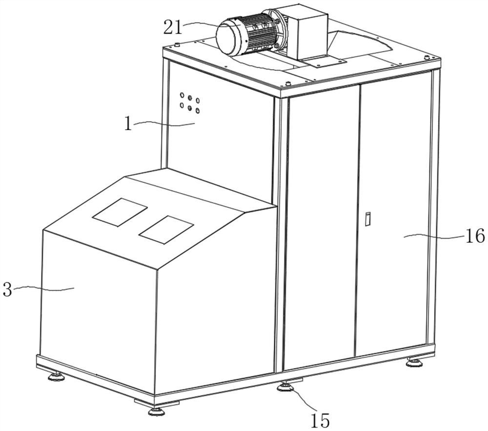
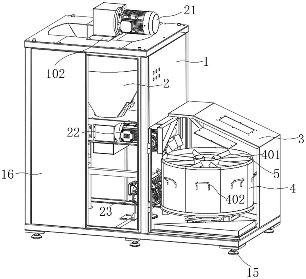
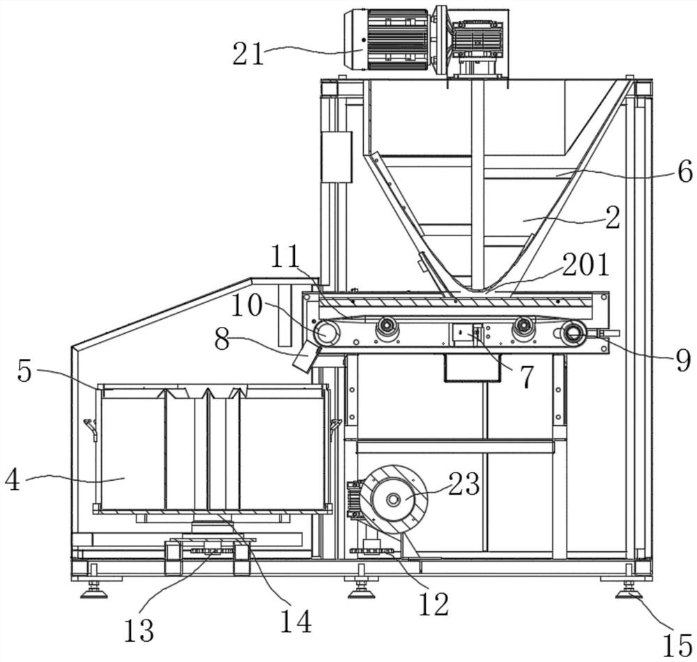
[0027] Such as Figure 1-5 As shown, a kind of wet coal sample mixing rotary shrinkage machine provided by the present invention includes a mixing casing 1, a mixing funnel 2 is arranged inside the mixing casing 1, and a discharge outlet is arranged at the lower end of the mixing funnel 2. Material port 201, the lower side of the discharge port 201 is provided with a conveyor belt 11; scraper plate 7, the scraper plate 7 is fixedly installed on the inner wall of the mixer shell 1 side, the scraper plate 7 is located between the upper and lower conveyor belts of the conveyor belt 11, and the outer wall on one side is in contact with the lower conveyor belt; the r


PUM


Abstract

The invention relates to a wet coal sample mixing rotary division machine which comprises a material mixing machine shell, a material mixing funnel is arranged in the material mixing machine shell, a discharging port is formed in the lower end of the material mixing funnel, and a conveying belt is arranged on the lower side of the discharging port; the scraping plate is fixedly installed on the inner wall of one side of the mixing machine shell and located between an upper conveying belt and a lower conveying belt of the conveying belt, and the outer wall of one side of the scraping plate makes contact with the lower conveying belt; the material receiving machine shell is located on one side of the material mixing machine shell, a separation material box is placed in the material receiving machine shell and located at the tail end of the conveying belt in the conveying direction, and an edge cover is movably installed on the outer wall of the upper side of the separation material box. The conveying belt drives feeding through a driving wheel and a transmission wheel at the two ends, the conveying belt is located at the upper end of the mixing hopper, a mixing rotating blade is arranged in the mixing hopper, and a mixing motor arranged at the top drives the mixing rotating blade to rotate to mix wet coal.

Description


Claims


Application Information

Patent Timeline
Owner 镇江市丰泰化验制样设备有限公司
Why Eureka
Try Eureka