Instantaneous frequency measurement system and method based on differential optical time stretching principle

A technology of time stretching and instantaneous frequency, which is applied in the transmission system, electromagnetic wave transmission system, electrical components, etc., can solve the problems that affect the accuracy of measurement results, high measurement cost, uneven pulse envelope, etc., and improve measurement accuracy , Eliminate the effects of distortion and reduce costs

Pending Publication Date: 2022-05-17
BEIJING JIAOTONG UNIV
View PDF0 Cites 0 Cited by
  • Summary
  • Abstract
  • Description
  • Claims
  • Application Information

AI Technical Summary

Benefits of technology

This patented method improves upon conventional methods for measuring electrical properties such as voltage or current without causing any problems like interference from other devices connected together through wired connections. It also allows multiple frequency measurements simultaneover with reduced costs compared to older techniques that require separate instruments. Overall, this technique helps improve both performance and efficiency during testing processes while reducing errors associated therewith.

Problems solved by technology

The technical problem addressed in this patented text is how quickly identify and locate specific carriers within radio waves without affecting their quality or performance during traditional electron beam search procedures like FSM. This requires accurate and efficient determination of these carriers' frequency content with minimal impacts upon other devices involved.

Method used


Image

  • Instantaneous frequency measurement system and method based on differential optical time stretching principle
  • Instantaneous frequency measurement system and method based on differential optical time stretching principle
  • Instantaneous frequency measurement system and method based on differential optical time stretching principle

Examples


Embodiment 1

[0024] Embodiment 1: The instantaneous frequency measurement method based on the principle of differential optical time stretching, by adopting a dual-output push-pull Mach-Zehnder modulator (DOMZM) with complementary outputs and a balanced photodetector to realize differential detection, suppressing due to laser spectrum The RF signal distortion caused by unevenness, the RF signal to be tested is firstly modulated onto the chirped pulse light, and then linearly widened in the time domain by the dispersion module, so that the analog bandwidth is compressed, and the high-speed signal can be realized with a low-speed digitizer quantized sampling.

[0025] Contains the following steps:

[0026] When the DOMZM is at the quadrature bias point, assuming the RF input signal is V(t), the output electric fields of the two complementary output terminals of the DOMZM can be expressed as:

[0027]

[0028] Among them, E 0 (t) represents the input optical signal, V π is the half-wave vo

Embodiment 2

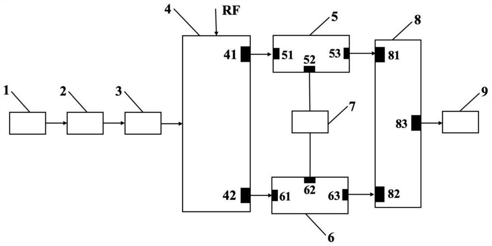
[0046] Embodiment 2: the instantaneous frequency measurement system based on the principle of differential optical time stretching, such as figure 1 As shown, it includes pulsed laser source 1, dispersion module 1 2, polarization controller 3, DOMZM 4, optical circulator 1 5 and optical circulator 2 6, dispersion module 2 7, balance detector 8 and real-time oscilloscope 9 .

[0047] The central wavelength of the light pulse output by the light source 1 used in this embodiment is 1565 nm, the laser pulse width is about 100 fs, the 3 dB bandwidth is 23 nm, and the repetition frequency is 100 MHz. The dispersion values ​​of the first dispersion module 2 and the second dispersion module 7 are -20 ps / nm and -150 ps / nm respectively, so according to the formula (5), the stretching factor of the system is 8.5. DOMZM 4 has a bandwidth of 20GHz, V π is 4.7V, the bandwidth of the balanced photodetector 8 is 10GHz, the bandwidth of the real-time oscilloscope 9 is 6GHz, and the sampling


PUM


Abstract

An instantaneous frequency measurement system based on a differential optical time stretching principle relates to the field of microwave photonics, ultrafast measurement and real-time measurement, and is characterized in that a light output end of a pulse laser light source is connected with one end of a dispersion module I, the other end of the dispersion module I is connected with an input end of a polarization controller, and an output end of the polarization controller is connected with a light input end of a modulator; one output port of the modulator is connected with the input end of the optical circulator I; the other output port of the modulator is connected with the input end of the optical circulator I, the other output port of the modulator is connected with the input end of the optical circulator II, the port of the optical circulator I and the port of the optical circulator II are respectively connected with one end of the dispersion module II, and the port of the optical circulator I and the port of the optical circulator II are respectively connected with the first optical input port and the second optical input port of the balance detector. The system can relieve the pressure of rear-end electronic equipment, eliminates the distortion influence of uneven laser pulse envelope on measurement through differential detection, and can perform real-time and accurate ultrafast measurement on multi-frequency signals.

Description


Claims


Application Information

Patent Timeline
Owner BEIJING JIAOTONG UNIV
Why Eureka
Try Eureka