Motion control system of robot mechanical arm, collaborative robot and storage medium
A motion control system and robot technology, applied in manipulators, program-controlled manipulators, manufacturing tools, etc., can solve problems such as rebound, jitter, and drift, and achieve the effect of flexible operation and jitter resolution.
- Summary
- Abstract
- Description
- Claims
- Application Information
AI Technical Summary
Problems solved by technology
Method used
Image

Examples
Example Embodiment
[0049] Example 1
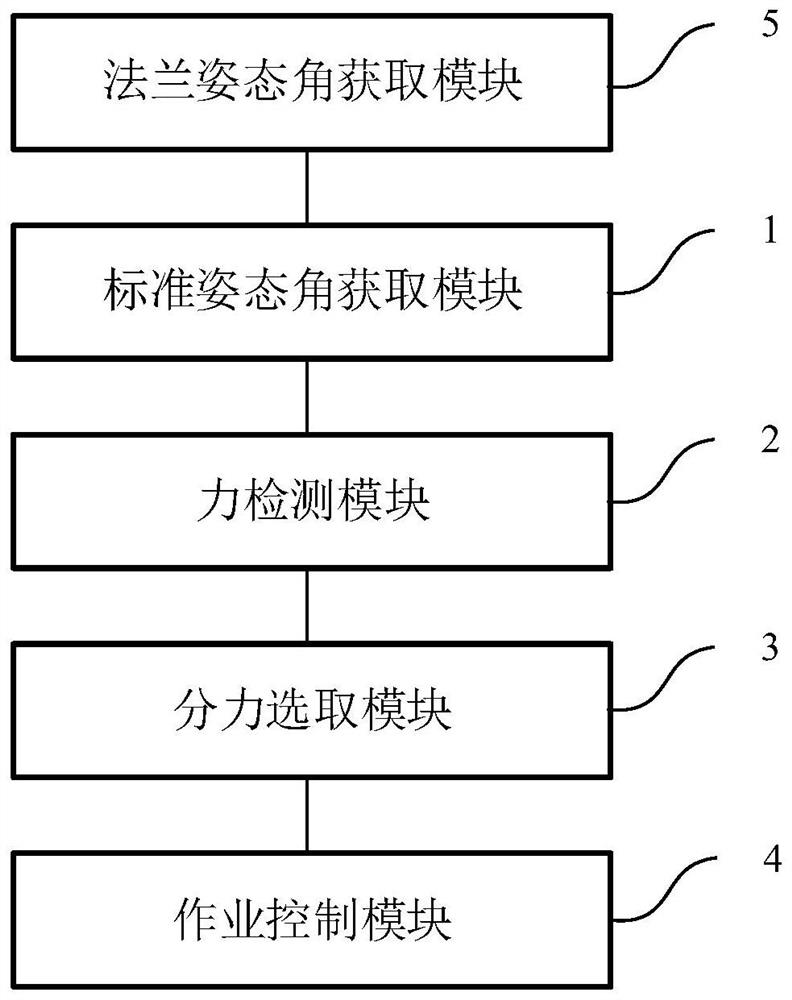
[0050] A motion control system for a robotic arm, the flange at the end of the robotic arm is provided with an end tool, such as figure 1 As shown, the motion control system includes:
[0051] The standard attitude angle acquisition module is used to acquire the standard Euler attitude angle of the current operation point when the next operation inflection point of the end tool in the robot coordinate system is the moving target;
[0052] a force detection module for real-time detection of the force acting on the end tool at the current operating point;
[0053] a component force selection module, configured to decompose the acting force into three angular directions of the standard Euler attitude angle, and select the acting component force toward the next work inflection point;
[0054] An operation control module, configured to control the end tool to move to the next operation inflection point based on the acting component force.
[0055] In this embodim
Example Embodiment
[0109] Example 2
[0110] A collaborative robot includes the motion control system of the robot arm according to the embodiment.
[0111] Figure 7 This is a schematic structural diagram of a collaborative robot provided in this embodiment. Figure 7 A block diagram of an exemplary collaborative robot 90 suitable for use in implementing embodiments of the present invention is shown. Figure 7 The displayed collaborative robot 90 is only an example, and should not impose any limitations on the functions and scope of use of the embodiments of the present invention.
[0112] like Figure 7 As shown, the collaborative robot 90 may take the form of a general-purpose computing device, which may be, for example, a server device. The components of the collaborative robot 90 may include, but are not limited to, at least one processor 91 , at least one memory 92 , and a bus 93 connecting different system components (including the memory 92 and the processor 91 ).
[0113] The bus 93 i
Example Embodiment
[0119] Example 3
[0120] A computer-readable storage medium on which a computer program is stored, and when the computer program is executed by a processor, a motion control method of the following robot manipulator is realized, a flange at the end of the manipulator is provided with an end tool, and the Methods include:
[0121] Obtain the standard Euler attitude angle of the current operating point when the next operating inflection point of the end tool in the robot coordinate system is the moving target;
[0122] real-time detection of the force acting on the end tool;
[0123] Decompose the acting force into three angular directions of the standard Euler attitude angle, and select the acting force component toward the next work inflection point;
[0124] The end tool is controlled to move to the next work inflection point based on the applied component force.
[0125] Wherein, the readable storage media may include, but are not limited to, portable disks, hard disks, ran
PUM
 Abstract
Description
Claims
Application Information
 - R&D Engineer
- R&D Manager
- IP Professional
- Industry Leading Data Capabilities
- Powerful AI technology
- Patent DNA Extraction
Browse by: Latest US Patents, China's latest patents, Technical Efficacy Thesaurus, Application Domain, Technology Topic.
© 2024 PatSnap. All rights reserved.Legal|Privacy policy|Modern Slavery Act Transparency Statement|Sitemap