Dual circular polarization sum-difference network

A dual-circular polarization, network technology, applied in antennas, antenna grounding devices, waveguides, etc., can solve problems such as increasing the difficulty of debugging, and achieve the effects of being less prone to external interference, increasing operating bandwidth, and small size

Pending Publication Date: 2022-07-15
XIAN UNIV OF POSTS & TELECOMM
View PDF0 Cites 0 Cited by
  • Summary
  • Abstract
  • Description
  • Claims
  • Application Information

AI Technical Summary

Benefits of technology

This patented technology describes two types of structures: one uses multiple layers for transmitting signals while another reduces space consumption or allows for better signal quality. It also includes various techniques such as balanced amplifiers (BAs) and strip lines to improve performance. Overall, this design provides technical benefits over existing designs.

Problems solved by technology

This patented solution involves combining different components into one module that can be easily installed on an aircraft's airborne radar system (Airport). These differences help improve signal quality for better detection performance during flight operations or other applications such as target recognition tracking.

Method used


Image

  • Dual circular polarization sum-difference network
  • Dual circular polarization sum-difference network
  • Dual circular polarization sum-difference network

Examples


Embodiment Construction

[0056] In order to make the purposes, technical solutions and advantages of the embodiments of the present invention clearer, the technical solutions in the embodiments of the present invention will be clearly and completely described below with reference to the accompanying drawings in the embodiments of the present invention. Obviously, the described embodiments These are some embodiments of the present invention, but not all embodiments. The components of the embodiments of the invention generally described and illustrated in the drawings herein may be arranged and designed in a variety of different configurations.

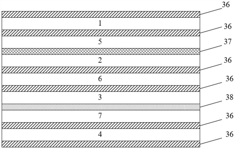
[0057] like figure 1 As shown, the present invention provides a double circularly polarized and differential network of striplines, comprising a first dielectric plate 1, a first adhesive plate 5, a second dielectric plate 2, a second adhesive Board 6 , third media board 3 , third adhesive board 7 and fourth media board 4 . Both sides of the first dielectric she


PUM


Abstract

The invention belongs to a sum-difference network, and provides a dual-circular-polarization sum-difference network in order to solve the technical problem that in an existing sum-difference network structure, modules are connected through cables, and the debugging difficulty is increased. Comprising a first dielectric plate, a first bonding plate, a second dielectric plate, a second bonding plate, a third dielectric plate, a third bonding plate and a fourth dielectric plate which are sequentially stacked, metal grounding structures are printed on the two sides of the first dielectric plate, the side, close to the second bonding plate, of the second dielectric plate, the side, close to the second bonding plate, of the third dielectric plate and the two sides of the fourth dielectric plate, and a levorotation sum-difference network structure is printed on the surface, close to the first bonding plate, of the second dielectric plate. A right-handed rotation sum-difference network structure is printed on the surface, close to the third bonding plate, of the third dielectric plate, feed holes are formed in the left-handed rotation sum-difference network structure on the second dielectric plate, and feed through holes which are communicated with one another are formed in the positions, corresponding to the feed holes, of the second bonding plate, the third dielectric plate, the third bonding plate and the fourth dielectric plate.

Description


Claims


Application Information

Patent Timeline
Owner XIAN UNIV OF POSTS & TELECOMM
Why Eureka
Try Eureka