Infusion device

An infusion device and infusion technology, applied in the directions of pressure infusion, hypodermic injection devices, instruments, etc., can solve the problems of deterioration, component wear, and difficulty in realizing the clamping effect of the infusion line.

Pending Publication Date: 2022-07-19
FRESENIUS KABI NANCHANG CO LTD
View PDF0 Cites 0 Cited by
  • Summary
  • Abstract
  • Description
  • Claims
  • Application Information

AI Technical Summary

Problems solved by technology

[0005] However, in multiple operations, the traditional liquid stop clamp mechanism is prone to wear and tear of components during switching, resulting in deterioration
Additionally, when the clamp mechanism is not properly positioned, the clamp mechanism will struggle to clamp the infusion line, causing medical fluids to flow through the infusion set in an undesired manner
[0006] In addition, traditional infusion sets have more connecting parts, which increases the production and assembly costs of the infusion set

Method used


Image

  • Infusion device
  • Infusion device
  • Infusion device

Examples


Embodiment Construction

[0049] The present invention will be described in detail below by means of exemplary embodiments with reference to the accompanying drawings. It should be understood that the following detailed description of the present invention is intended for purposes of illustration only and not limitation of the invention and its application or uses.

[0050] Orientation terms such as "upper", "lower", "left", "right" and the like used in the specification are only intended for the purpose of clear illustration in conjunction with the accompanying drawings, and are not intended to limit the orientation of related components . In practice, the positional orientation relationship between the components may vary depending on the specific application.

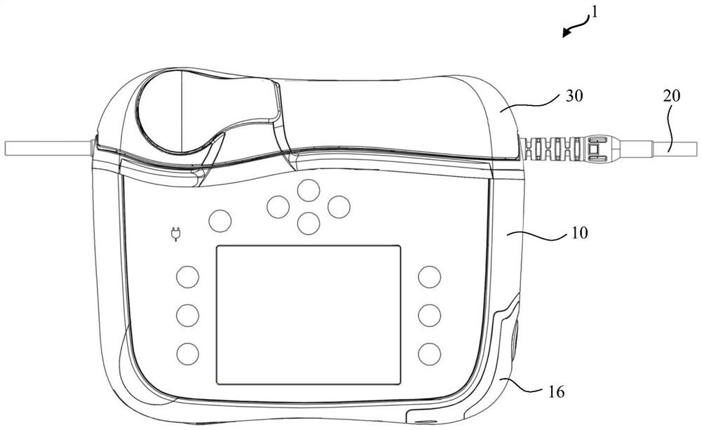
[0051] figure 1 A view of an infusion device 1 according to an embodiment of the invention in the working state is shown schematically. like figure 1 As shown, the infusion set 1 includes: a body 10 configured to receive the internal comp...


PUM


Abstract

The present application provides an infusion device comprising: a body configured to receive an infusion line and comprising a pumping mechanism configured to flow a medical fluid through the infusion line received in the body; a pump door assembly configured to be connected to the body for closing the body, and configured to fix the infusion line in place in the body, the pump door assembly including a snap member including: snap projections disposed at both ends of the snap member in a longitudinal direction of the snap member, the snap projections being configured to engage the infusion line in the body; the top surface of the buckle protruding part is shaped to be suitable for receiving an infusion pipeline; and the groove is located in the middle position between the buckle protruding parts and is configured to be sunken to be lower than the buckle protruding parts in the height direction of the buckle component.

Description

technical field [0001] The present application relates to infusion devices for delivering medical fluids, such as drugs or nutritional solutions, to patients. Background technique [0002] Infusion devices, such as volumetric (peristaltic) infusion devices, are used to precisely deliver medical fluids, such as drugs or nutritional solutions, to a patient at a predetermined rate. An infusion line passing through an infusion set in which a pumping mechanism, for example in a peristaltic manner, is infusion, is connected at one end to, for example, a container containing a medical fluid and at the other end to a patient. A pumping force is applied to the infusion line, causing the fluid to be delivered through the infusion line toward the patient. [0003] Typically, in order to better secure the positioning of the infusion line within the infusion set, a snap-fit ​​feature is provided within the infusion set for securing the infusion line in place. However, on the one hand, ...

Claims


Application Information

Patent Timeline
IPC IPC(8): A61M5/142A61M5/168A61M5/36
CPCA61M5/142A61M5/16813A61M5/365A61M5/16831A61M5/16881A61M2205/3334A61M2205/18
Inventor 胡庆邹镇中徐坚刘发杰
Owner FRESENIUS KABI NANCHANG CO LTD
Why Eureka
Try Eureka