Combined type pipeline fixing support
A fixed pipeline and combined technology, which is applied in the direction of pipeline supports, pipes/pipe joints/fittings, mechanical equipment, etc., can solve problems such as height difference, complex pipeline installation engineering, and influence on normal pipeline installation, so as to ensure normal operation and avoid height difference effect
- Summary
- Abstract
- Description
- Claims
- Application Information
AI Technical Summary
Problems solved by technology
Method used
Image

Examples
Example Embodiment
[0027] Example 1
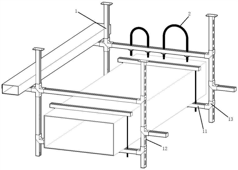
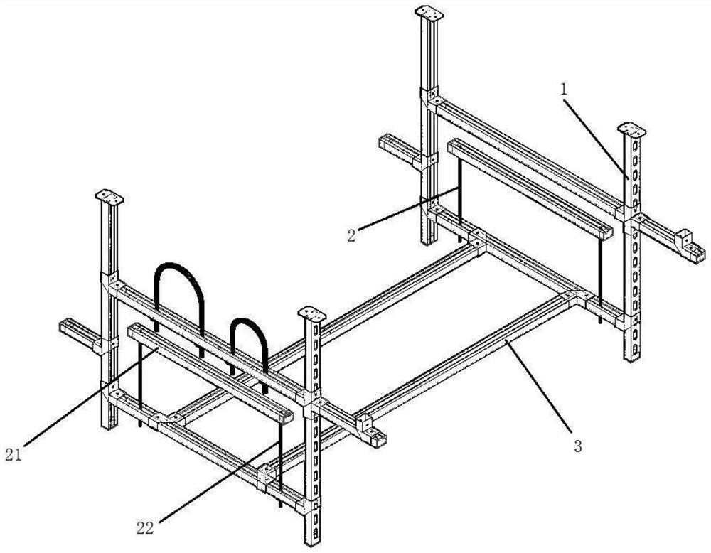
[0028] like figure 1 , figure 2 shown, figure 1 It is a view of the installation structure of the combined fixed pipe support; figure 2 It is a three-dimensional structural view of the combined fixed pipe support.
[0029] The combined fixed pipe support of the present invention includes a main body support group, the main body support group includes an adjustment frame 1 and a locking frame 2, the adjustment frame 1 is fixedly arranged on the ceiling of the building, the locking frame 2 and the adjustment frame 2 The frame 1 is connected to form a locking cavity, and the pipe body is arranged in the locking cavity to realize the fixing construction of the horizontal pipeline.
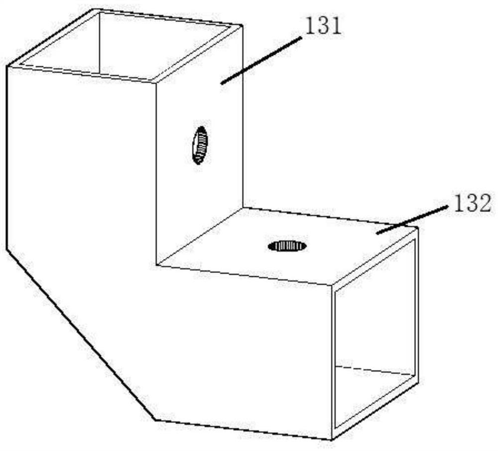
[0030] Specifically, the adjusting frame 1 includes a hosting 11 , a hanging pipe 12 and a corner piece 13 , one end of the hanging pipe 12 is vertically fixed on the ceiling of the building, and the hosting 11 is connected to the The hanging pipe 12 is fixedly connected, the loc
Example Embodiment
[0039] Embodiment 2
[0040] like Figure 4 shown, Figure 4 It is a schematic structural diagram of the combined fixed pipe bracket for fixing the square pipe; in this embodiment, the locking rod is used to fix the square pipe, and the locking rod includes a pressure rod 21 and a hanger rod 22. The ends are respectively connected to the pressure rod 21 and the hosting 11, the two hanging rods 22 arranged in parallel are surrounded by the pressing rod 21 and the hosting 11 to form the locking cavity, and the two hanging rods arranged in parallel The distance between 22 is set in coordination with the side length of the pipe body to be fixed.
[0041]The pressure rod 21 is provided with a third adjustment groove, both ends of the hanger rod 22 are provided with a first threaded section, and both first threaded sections are threadedly connected with a first threaded nut. The upper end of the suspension rod 22 passes through the third adjustment groove, the first threaded nut on
Example Embodiment
[0043] Embodiment 3
[0044] like Figure 5 shown, Figure 5 It is a schematic diagram of the structure of the combined fixed pipe bracket for fixing the circular pipe; in this embodiment, the locking rod is used to fix the circular pipe, and the locking rod is set as a U-shaped rod.
[0045] Preferably, the locking rod includes a circular arc segment and two adjusting segments, the two adjusting segments are arranged in parallel, and the two adjusting segments are respectively connected with both ends of the circular arc segment.
[0046] The circular arc segment on the locking rod and the hosting 11 are surrounded to form the locking cavity, and the diameter of the circular arc segment of the locking rod is consistent with the diameter of the pipe body to be fixed, so as to realize the safety of the pipe body. fixed.
[0047] A second thread segment is provided on both of the adjustment segments, a second adjustment nut is threadedly connected to the second thread segment, t
PUM
 Abstract
Description
Claims
Application Information
 - R&D Engineer
- R&D Manager
- IP Professional
- Industry Leading Data Capabilities
- Powerful AI technology
- Patent DNA Extraction
Browse by: Latest US Patents, China's latest patents, Technical Efficacy Thesaurus, Application Domain, Technology Topic.
© 2024 PatSnap. All rights reserved.Legal|Privacy policy|Modern Slavery Act Transparency Statement|Sitemap