Internal circulation type thermal power generation system

An internal circulation and generator technology, applied in steam generation, machine/engine, liquid variable capacity machinery, etc., can solve the problems of lack of oxygen, low fuel combustion efficiency, and long time required for the temperature of the combustion furnace, so as to reduce costs, The effect of increasing combustion efficiency

Pending Publication Date: 2022-07-29
叶经碧
View PDF0 Cites 0 Cited by
  • Summary
  • Abstract
  • Description
  • Claims
  • Application Information

AI Technical Summary

Problems solved by technology

[0004] When the fuel is burned in the furnace, the lack of oxygen is often caused by the slow air circulation inside the furnace body, which makes the fuel combustion efficiency low and the combustion furnace takes too long to reach the required temperature.

Method used


Image

  • Internal circulation type thermal power generation system
  • Internal circulation type thermal power generation system
  • Internal circulation type thermal power generation system

Examples


Example Embodiment

[0027] The technical solutions in the embodiments of the present invention will be clearly and completely described below with reference to the accompanying drawings in the embodiments of the present invention. Obviously, the described embodiments are only a part of the embodiments of the present invention, rather than all the embodiments. Based on the embodiments in the present invention, all other embodiments obtained by those of ordinary skill in the art under the premise of not making creative work all belong to the scope of protection of the present invention:

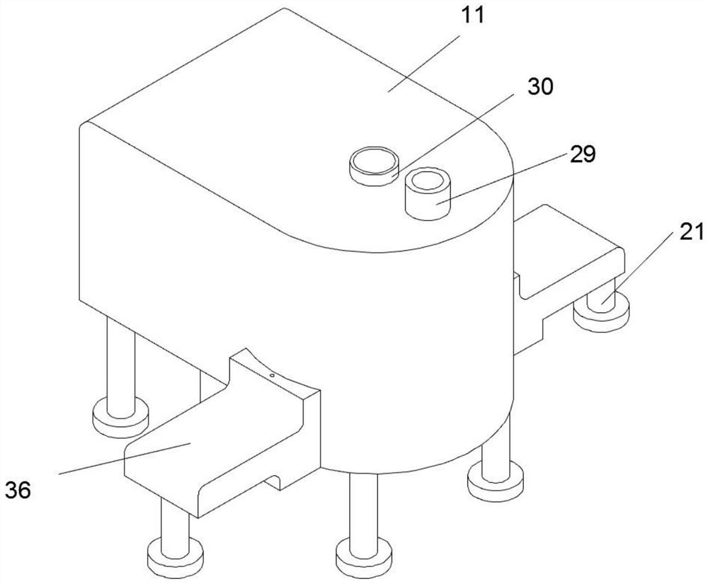
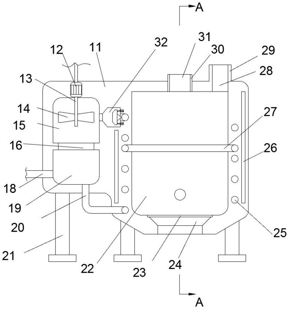
[0028] Refer to the attached Figure 1-Figure 8 , according to an embodiment of the present invention, an internal circulation type thermal power generation system includes a body 11, a feed box 30 is fixed on the upper end surface of the body 11, and a smoke exhaust box 29 is fixed on the right side of the feed box 30 , the body 11 is provided with a power generation chamber 15, the right side of the power generatio


PUM


Abstract

The invention relates to the technical field of thermal power generation, in particular to an internal circulation type thermal power generation system which comprises a machine body, a feeding box fixedly arranged on the upper end face of the machine body, a smoke exhaust box fixedly arranged on the right side of the feeding box, a power generation cavity formed in the machine body, a combustion cavity formed in the right side of the power generation cavity and a heating pipeline arranged in the outer circular wall of the combustion cavity. A feeding cavity communicating with the combustion cavity is formed in the upper end face of the feeding box, and a smoke discharging cavity communicating with the combustion cavity is formed in the upper end face of the smoke discharging box. The circulating air blowing devices are installed at the front end and the rear end of the machine body, so that the temperature in the furnace is not affected by the external environment temperature in the air blowing process, and the function of improving the combustion efficiency in the furnace can be achieved.

Description


Claims


Application Information

Patent Timeline
Owner 叶经碧
Why Eureka
Try Eureka