Low-temperature casing pressure device for taking out covered stent

A stent-graft and low-temperature technology, which is applied in the direction of spraying device, paint spraying room, etc., can solve problems such as removal of stent-graft, and achieve the effect of improving production efficiency and saving labor.

Active Publication Date: 2022-08-05
深圳库珀医疗股份有限公司
View PDF6 Cites 2 Cited by
  • Summary
  • Abstract
  • Description
  • Claims
  • Application Information

AI Technical Summary

Benefits of technology

This technology helps cool down the covering layer on medical devices like blood vessels or other tubular structures made up mostly of metal that are used inside body cavities during surgery. By adding these layers together with certain mechanisms such as tissue removal tools, it makes them easier to remove without damaging their structure.

Problems solved by technology

This technical problem addressed in this patented text relates to producing thin metallic coatings that are suitable for use inside medicine device's lumens or blood vessel systems without requiring complex processes like bonding them separately.

Method used


Image

  • Low-temperature casing pressure device for taking out covered stent
  • Low-temperature casing pressure device for taking out covered stent
  • Low-temperature casing pressure device for taking out covered stent

Examples


Embodiment Construction

[0021] In order to further illustrate the various embodiments, the present invention provides accompanying drawings, which are part of the disclosure of the present invention, and are mainly used to illustrate the embodiments, and can be used in conjunction with the relevant descriptions in the specification to explain the operation principles of the embodiments. For these, those of ordinary skill in the art will understand other possible implementations and the advantages of the present invention. Components in the figures are not drawn to scale, and similar component symbols are generally used to represent similar components.

[0022] The specific embodiments of the present invention will be further described below with reference to the accompanying drawings. It should be noted here that the descriptions of these embodiments are used to help the understanding of the present invention, but do not constitute a limitation of the present invention. In addition, the technical featur


PUM

PropertyMeasurementUnit
Angleaaaaaaaaaa

Abstract

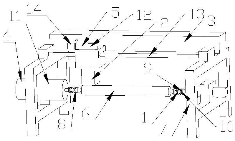
The invention discloses a low-temperature casing pressure device for taking out a covered stent, which comprises a traction mechanism for pulling a covered roll with the covered stent to advance, a compression mechanism for radial compression, a liquid nitrogen mechanism for enabling the covered roll with the covered stent to generate low temperature, a shell and a control panel, wherein the traction mechanism, the compression mechanism and the liquid nitrogen mechanism are all arranged in the machine shell, the compression mechanism comprises a compression motor, a worm gear, a worm and a radial compression plate, the compression motor drives the worm to rotate, the worm drives the worm gear to rotate, and the worm gear drives the radial compression plate to move in the radial direction. By arranging the traction mechanism, the compression mechanism, the liquid nitrogen mechanism, the machine shell and the control panel, the film covering roller of the film covering support is separated from the film covering support after being cooled and shrunk, the film covering support is taken down from the film covering roller under the action of the compression mechanism, labor is saved, and the production efficiency is improved.

Description


Claims


Application Information

Patent Timeline
Owner 深圳库珀医疗股份有限公司
Why Eureka
Try Eureka