Spin winding machine

A coiling machine and mechanical technology, applied in the direction of conveying filamentous materials, thin material processing, transportation and packaging, etc., can solve the problem of deterioration of the tracking performance of the contact roller 143, failure to check the slide box 144 easily, and damage the slide box 144 smoothly In order to achieve the effect of easy lifting abnormality, simple structure and low cost

Inactive Publication Date: 2002-06-12
MURATA MASCH LTD
View PDF2 Cites 7 Cited by
  • Summary
  • Abstract
  • Description
  • Claims
  • Application Information

AI Technical Summary

Benefits of technology

This patented technology allows for accurate measurement of smaller loads without requiring expensive equipment such as pressure sensors. By placing both the contactor rollers and an offload sensor below each other within certain limits, this system becomes less complex than traditional systems due to fewer components needed. Additionally, if some specific points are significantly different from normal conditions (such as low tension) then they may indicate possible issues during operation. Overall, these technical improvements make the monitoring process easier and faster while reducing costs associated with conventional methods used to measure them.

Problems solved by technology

This patented describes different technical problem addressed during manufacturing processes for making packages called Spin Weld Packages: It requires accurate monitoring of contact press force applied through various components like bearings supporting the contact point and carrying out feedback controls based upon changes detected from signals obtained via sensors attached to the bearings themselves. However, current methods have limitations due to their complexity and difficulty achieving stable operation under extreme conditions.

Method used


Image

  • Spin winding machine
  • Spin winding machine
  • Spin winding machine

Examples


Embodiment Construction

[0044] Embodiments of the present invention will be described below with reference to the drawings.

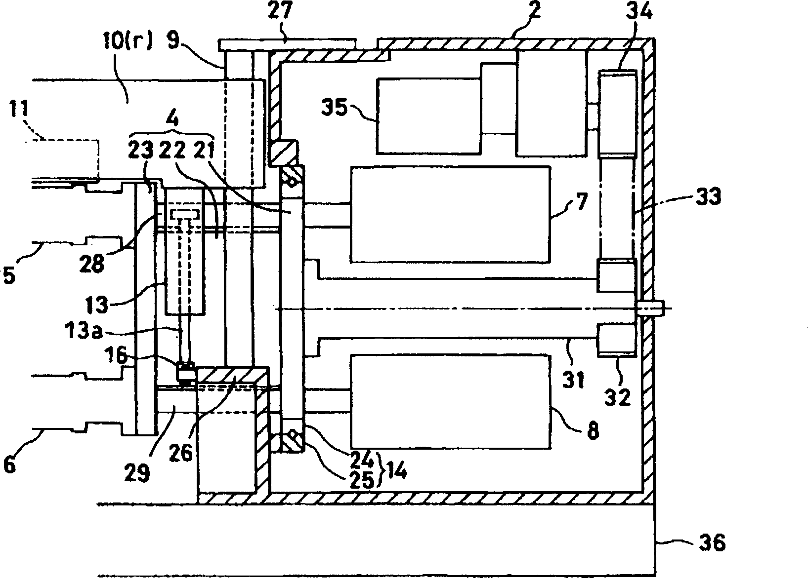
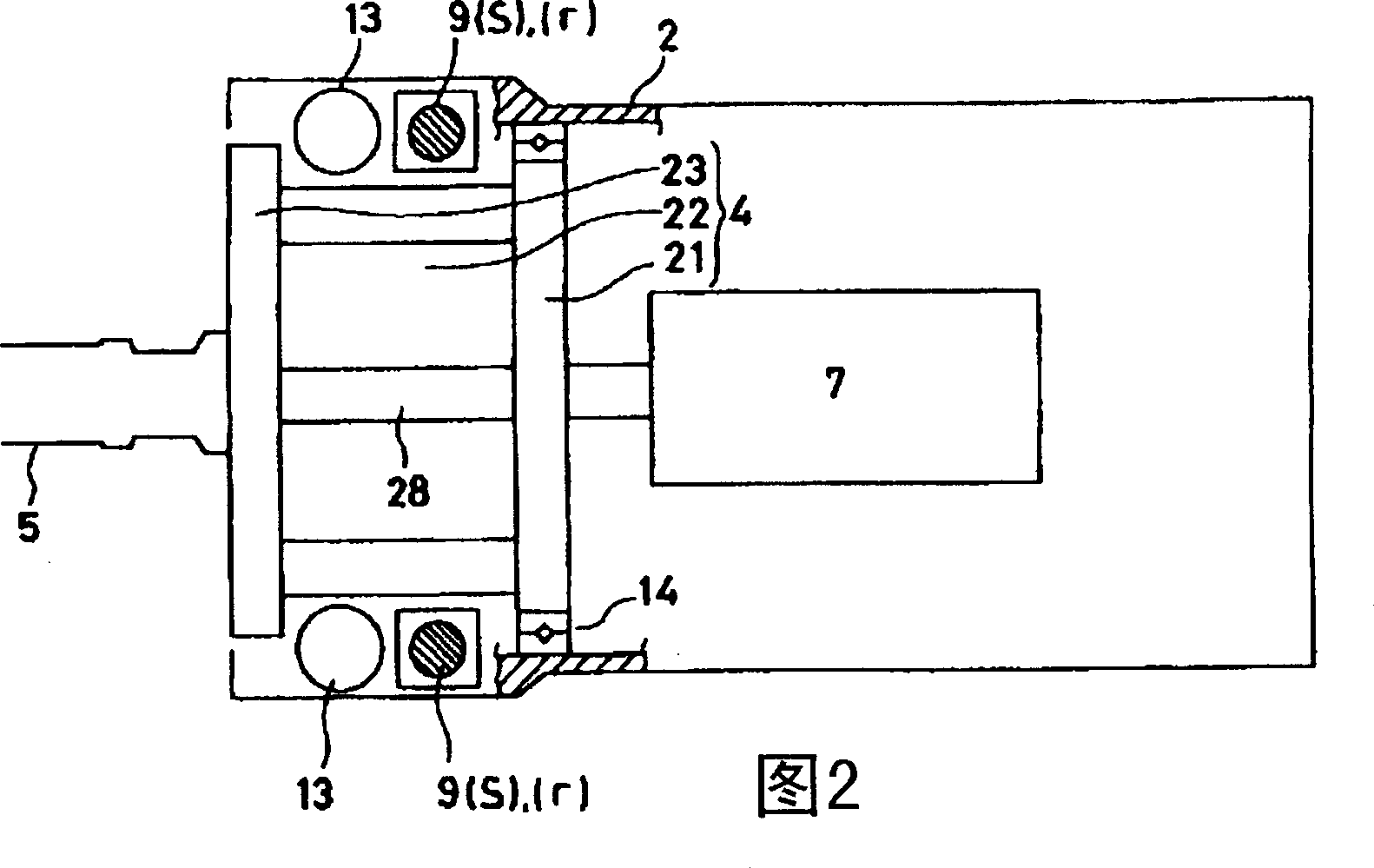
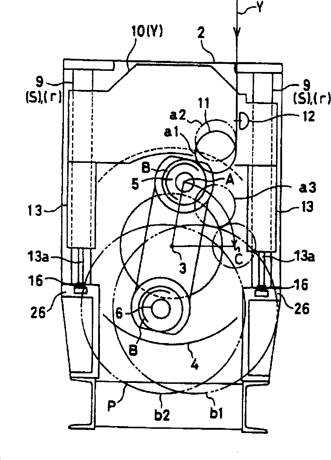
[0045] Such as Figure 4 , Figure 5 As shown, the spinning winder 1 is composed of the following parts: a turntable 4 that rotates around a central axis 3 relative to the machine body 2; two bobbin holders 5, 6 protruding from the turntable 4; The induction motors 7 and 8 driven by bobbin holders 5 and 6 on the back of the turntable 4; guided by the guide pillars 9 in the machine body 2, the lifting frame 10 that moves vertically up or down; the lifting frame 10 supported on the lifting frame 10 Contact roller 11; traverse device 12 supported on lifting frame 10.

[0046]The entire weight of the elevating frame 10 supporting the contact roller 11 and the traverse device 12 is supported by the contact pressure cylinder 13 provided between the elevating frame 10 and the machine body 2, and the difference between these weights and the upward thrust from the contact pressure cylin


PUM


Abstract

The object of the present invention is to obtain a contact pressure control device capable of carrying out feedback control enduring a practical use by inventing a pressure detecting means and the employment structure of the same. The contact pressure control device of the take-up winder comprises a bobbin holder 5, a contact pressure roller 11 contacted against the bobbin B set on the bobbin holder 5, a slide supporting mechanism (s) for supporting the contact pressure roller elevating or descending to the machine main body 2 , and a contact pressure cylinder 13 freely adjusting the contact pressure of the contact pressure roller 11 and the bobbin holder 5. Moreover, a load cell 16 is provided directly below one contact pressure cylinder 13 located between a pair of slide supporting mechanisms (s), (s). Furthermore, a print circuit board for controlling is provided for controlling the contact pressure cylinder 13 based on the detected value of the load cell 16 so that the contact pressure is to be maintained at a designated value.

Description


Claims


Application Information

Patent Timeline
Owner MURATA MASCH LTD
Why Eureka
Try Eureka