Dropping type safety decompression device

A pressure relief device and safety technology, applied in the direction of safety valve, valve device, functional valve type, etc., can solve the problems of high cost, complex manufacturing process, poor sealing performance of rupture disc, etc., and achieve simple manufacturing method and high sealing requirements. , the effect of low cost

Inactive Publication Date: 2004-07-21
DALIAN UNIV OF TECH
View PDF2 Cites 5 Cited by
  • Summary
  • Abstract
  • Description
  • Claims
  • Application Information

AI Technical Summary

Benefits of technology

This new type of safety valve has several technical features that are suitable for use at very small pressur levels while still being effective against leakage without adding extra weight or complexity compared with existing designs.

Problems solved by technology

This patented technical solution described by these inventors relates to improving the quality of security features made from hydronic system components such as explosion valves or pumps when exposed during normal use under extreme conditions like excessive water levels due to accidents involving oil spills. These improvements involve incorporating special materials into the design to improve its resistance against damage caused by external factors such as impact force and vibration.

Method used


Image

  • Dropping type safety decompression device
  • Dropping type safety decompression device
  • Dropping type safety decompression device

Examples


Embodiment Construction

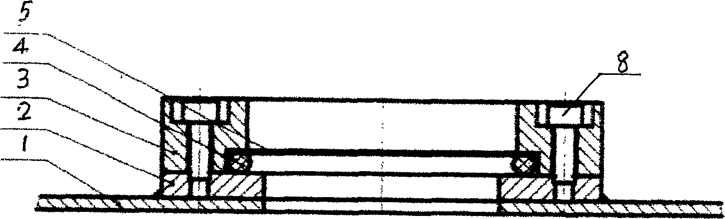
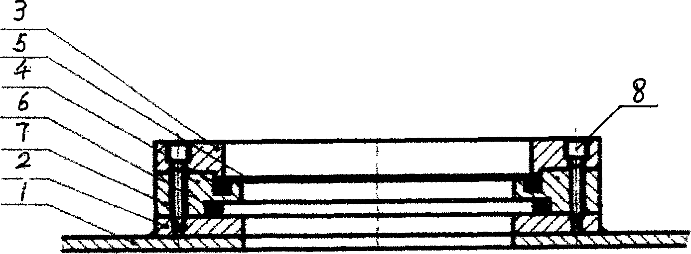
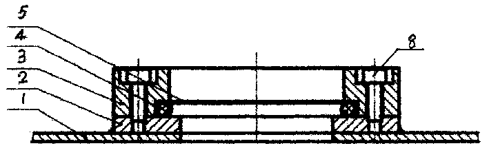
[0010] The present invention will be further described below with reference to the accompanying drawings.

[0011] A detachable safety pressure relief device according to the present invention is installed on the storage tank shell 1 . The operating pressure of the storage tank is 0.04MPa, and the design pressure is 0.25Mpa. Accordingly, the design pressure of the present invention is 0.1Mpa, and the discharge diameter is 240mm. The inner diameter of the upper page 3 of the holder is 255mm, the inner diameter of the container flange and the lower page 2 of the holder is 240mm, the outer diameter of the peeling piece 5 is 260mm, the thickness of the peeling piece 5 is 0.8mm, and the inner diameter of the O-ring 4 is 250mm , the outer diameter of the O-ring 4 is 262mm, and the deformation of the O-ring 4 after clamping is 3mm. After assembly, it is correctly installed on the tank shell 1, and it can work normally.

[0012] When the storage tank is overpressured, under the set bu


PUM


Abstract

A device is composed of holder upper limb, knockout sheet O shaped ring, container flange and holder down limb. The holding force between holder and knockout sheet is controlled by elastic deformation size of O shaped ring to ensure knocked out to knockout sheet at the designed explosive pressure. The internal diameter of holder upper limb is in between internal and external diameters of O shaped ring, axial distance of explosive sheet and upper limb contact surface of holder is 2-10 mm, at normal operating state holder upper limb remains contact state with holder down limb and container flange to ensure elastic deformation size of O shaped ring.

Description


Claims


Application Information

Patent Timeline
Owner DALIAN UNIV OF TECH
Why Eureka
Try Eureka