Control method of rail traffic infrared video frequency transmission system
A technology for video transmission system and rail transit, which is applied to TV systems adapted to optical transmission, cable transmission adaptation, transportation and packaging, etc. It can solve problems such as low reliability, high requirements, and complex technology, and achieve simple installation and commissioning and work. Reliable, System-Simple Effects
- Summary
- Abstract
- Description
- Claims
- Application Information
AI Technical Summary
Problems solved by technology
Method used
Image

Examples
Embodiment 1
[0038] The control method of the infrared video transmission system when the track is a straight line:
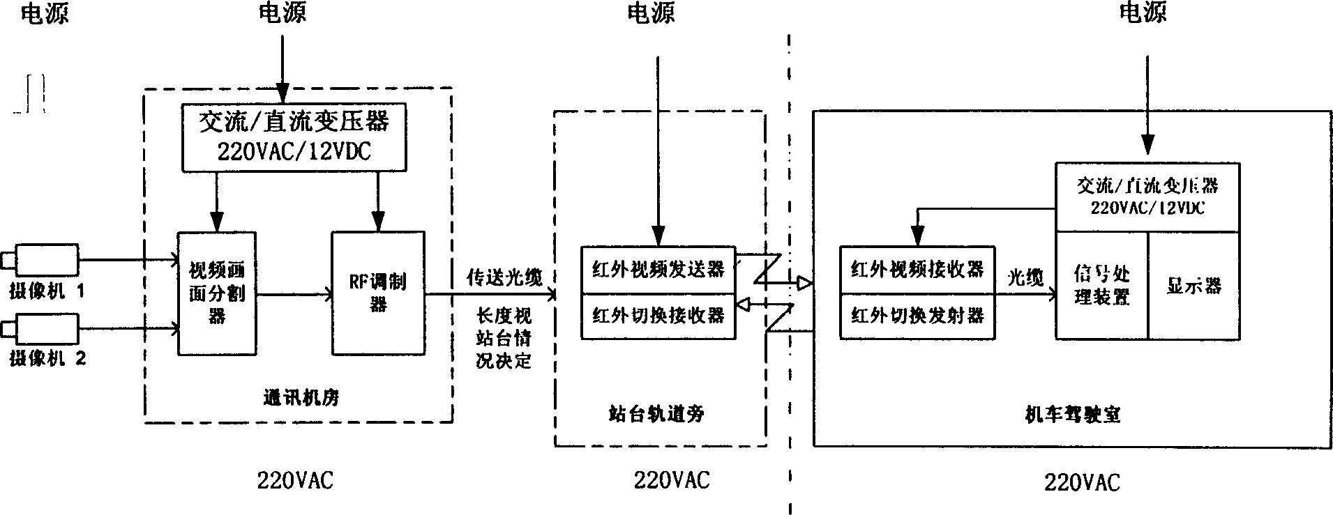
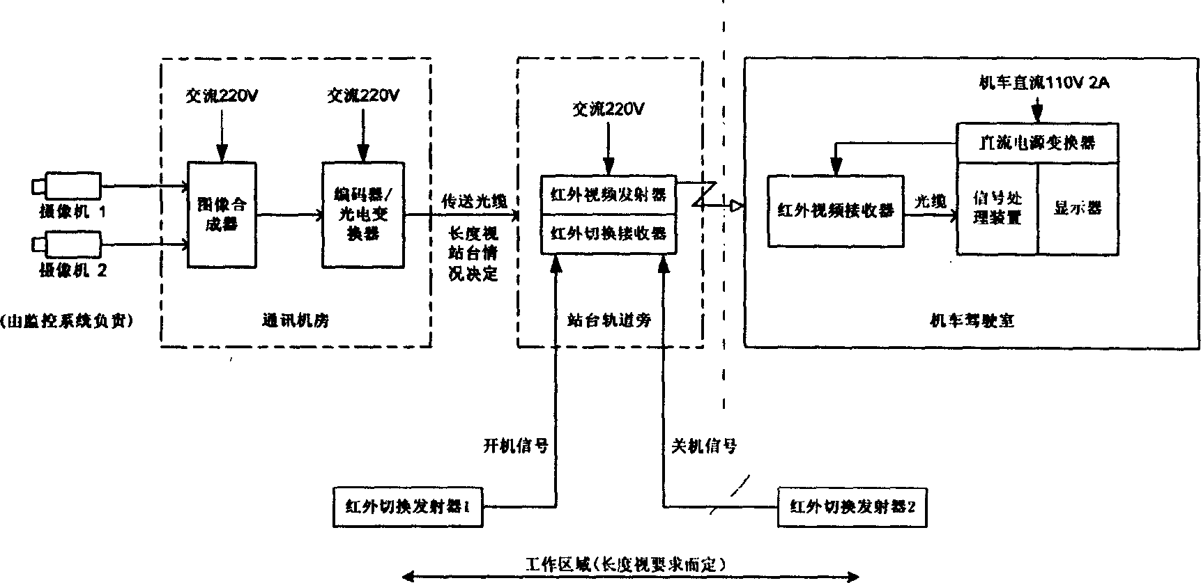
[0039] Such as Figure 6 Shown is the working principle diagram of the infrared video transmission system when the track is a straight line. The camera is installed on the platform; the image synthesizer and modulator are installed in the communication room; the infrared video receiver is installed behind the windshield of the locomotive cab. It is installed towards the direction of train movement. The monitor is installed on the left side of the bridge, and the infrared video transmitter needs to be installed on the pillars or walls beside the tracks at both ends of the platform. The installation height should be the same as that of the infrared video receiver on the locomotive, about 2 meters above, to prevent being blocked by people , detector 1 is installed 100 meters before the parking position of the platform, and detector 2 is installed 100 meters behind the parking po
Embodiment 2
[0041] The control method of the infrared video transmission system when the track is a curve:
[0042] Such as Figure 7 As shown, it is the working principle diagram of the infrared video transmission system when the track is a curve. N detectors are installed beside the curved track. The first detector is responsible for starting the first infrared video transmitter, and the second detector is responsible for The shutdown of the first infrared transmitter and the startup of the second infrared transmitter, and so on, the Nth detector is responsible for the shutdown of the Nth infrared video transmitter. The distance between the detectors depends on the size of the arc, the more curved the arc, the denser the detectors are packed. The locomotive detector makes the infrared video transmitter be in the relay working state like this. Other methods are the same as in Example 1.
PUM
 Abstract
Description
Claims
Application Information
 - R&D Engineer
- R&D Manager
- IP Professional
- Industry Leading Data Capabilities
- Powerful AI technology
- Patent DNA Extraction
Browse by: Latest US Patents, China's latest patents, Technical Efficacy Thesaurus, Application Domain, Technology Topic.
© 2024 PatSnap. All rights reserved.Legal|Privacy policy|Modern Slavery Act Transparency Statement|Sitemap