Non-volatile memory, method of manufacture, and method of programming

A memory cell, read-only memory technology, used in static memory, read-only memory, semiconductor/solid-state device manufacturing, etc., can solve problems such as power consumption and cross-leakage of adjacent cells, and achieve the effect of fast access

Inactive Publication Date: 2005-02-16
FREESCALE SEMICON INC
View PDF0 Cites 4 Cited by
  • Summary
  • Abstract
  • Description
  • Claims
  • Application Information

AI Technical Summary

Benefits of technology

The technical effect that this technology improves upon previous methods by allowing some parts of it to have faster access speeds than others. This means they can handle more data quickly without slowing down or even losing their power supply altogether.

Problems solved by technology

Technological Problem: Current Solid State Random Access Memories (RAM) use binary data storage technology called EMLC's (electronic randomaccess memristors). These RAM devices require large amounts of energy per unit area compared to traditional semiconductor technologies like silicon integrated circuits due to limitations on how fast the necessary write current needs to flow through them. Additionally, there is often overlap areas where different components cannot operate correctly if one component operates faster but another component does not work properly. Overlapping regions further complicates the process of writing into these systems.

Method used


Image

  • Non-volatile memory, method of manufacture, and method of programming
  • Non-volatile memory, method of manufacture, and method of programming
  • Non-volatile memory, method of manufacture, and method of programming

Examples


Embodiment Construction

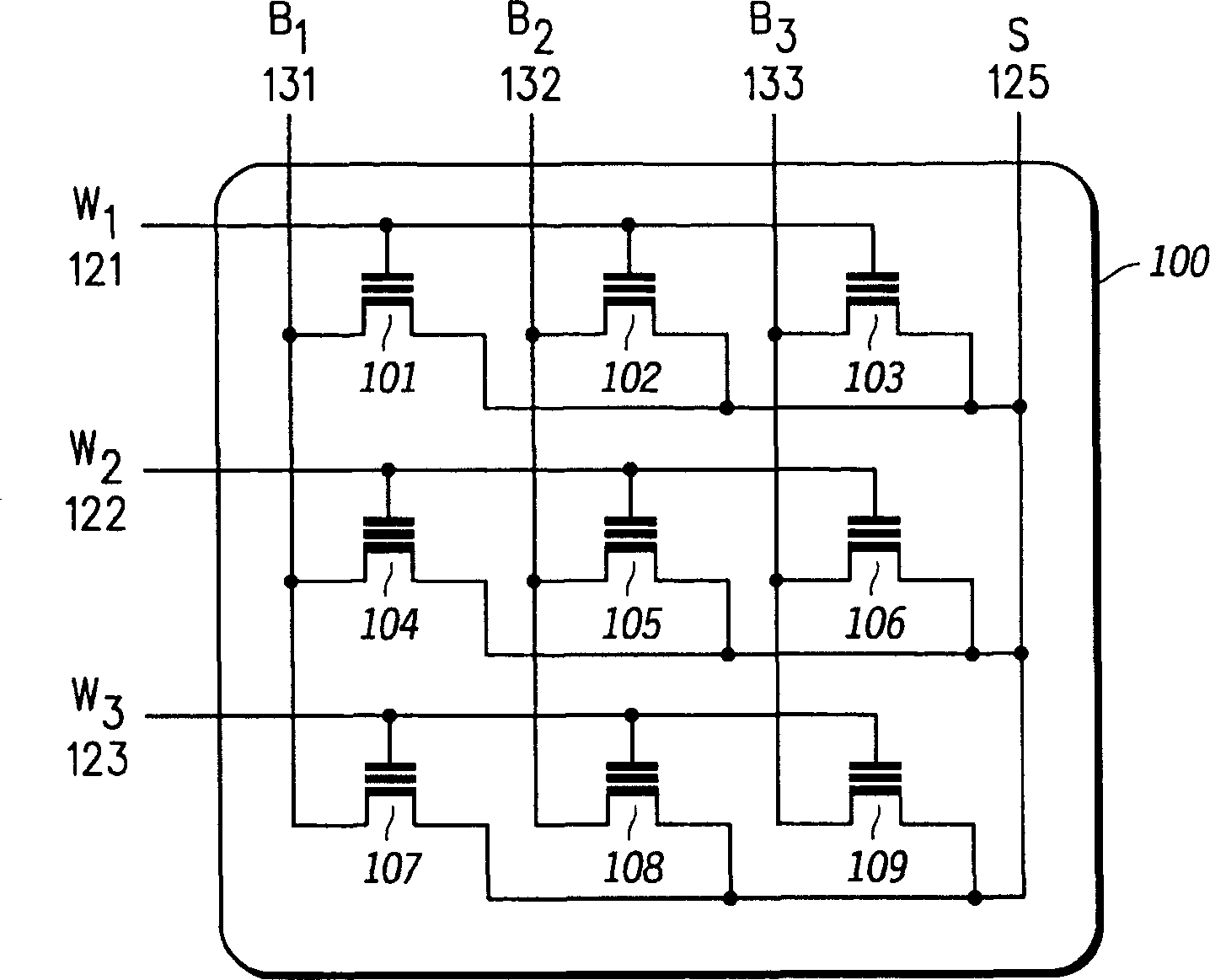
[0024] According to one embodiment of the invention, a nonvolatile memory (NVM) array, such as an Electrically Erasable Programmable Read Only Memory (EEPROM) array, includes columns of memory cells formed in separate p-well regions to The programming threshold voltage distribution width of selected memory cells in the array is reduced. For example, multiple memory cells sharing a common bit line are formed within a well region such as a p-well region. In one embodiment, each isolated p-well forms a column of memory cells in the array. The p-wells are electrically isolated from each other using shallow trench isolation (STI) structures. Memory cells formed in individual p-well regions share a common bit line and a common source line. Isolating the memory array into individual p-wells improves programming control by allowing the memory cells of the array to be programmed into a tight threshold voltage distribution.

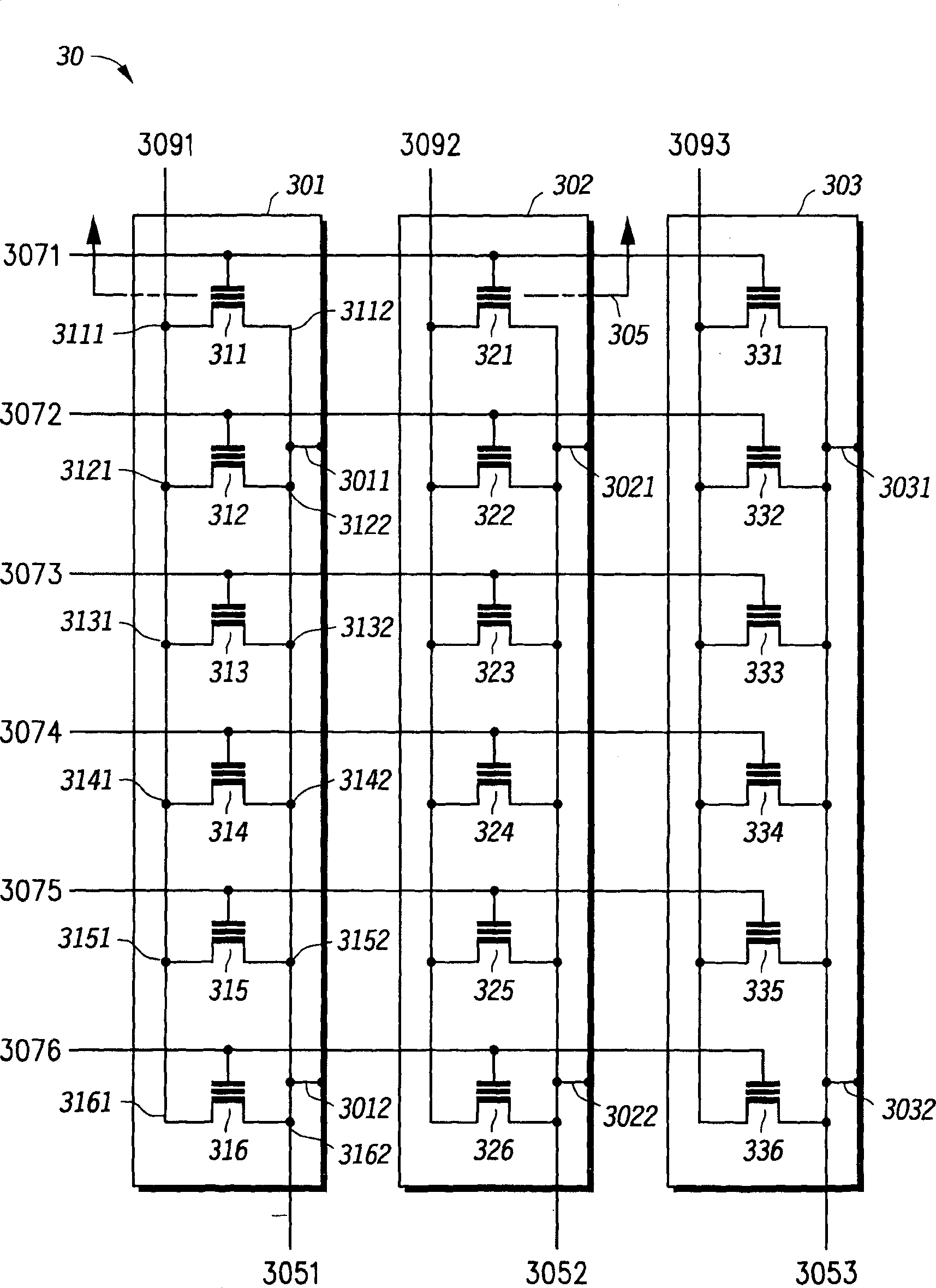
[0025] refer to image 3 , the memory cell array 30 includes


PUM


Abstract

A non-volatile memory includes an array (30) of cells in rows and columns (311-316; 331-336),where the cells of each column (311-316; 331-336) are positioned within a respective isolated p-well region (301, 302, 303). Control gates of sequential memory cells in rows of the array (311, 321, 331; 316, 316, 336) are electrically coupled by common wordlines (3071, 3072 3076). Bitlines (3091, 3092, 3093) electrically couple drain or source regions of each memory cell in the respective columns (311-316; 331-336). The source lines (3051, 3052, 3053) and at least one memory cell in each column of the array (311-316; 331-336) are electrically coupled to the p-well region (301, 302, 303) corresponding to the column of the source line and cell. Each column of the array (30) is therefore located within an isolated well.

Description


Claims


Application Information

Patent Timeline
Owner FREESCALE SEMICON INC
Why Eureka
Try Eureka