Dual-port physical separated card

An isolation card, dual network port technology, applied in the field of network security, can solve the problems of high computer cost, compatibility problems, difficult to apply to the market, etc., and achieve the effect of powerful function expansion, convenient and effective use, and high degree of security.

Inactive Publication Date: 2006-04-05
CATECH TECH
View PDF0 Cites 0 Cited by
  • Summary
  • Abstract
  • Description
  • Claims
  • Application Information

AI Technical Summary

Benefits of technology

This patented technology allows multiple computers within range (called clients) connected together without having them share any sensitive or secret material like files over internet protocol). It achieves this separation by providing special hardware devices called gateways which allow both types of machines to communicate securely while still allowing each other to freely choose what kind of resource they want to connect. By implementing this system, companies cannot easily compromise their private assets if needed due to potential leaks into unsecured areas where critical infrastructure may require protection against attacks such as deny service requests.

Problems solved by technology

Technics Problems In this patented method include how to prevent unauthorized access from remote devices connected over networks without physically separating them by creating an isolated environment with only one type of device attached at each end (hard drive). Additionally, there may exist other ways to protect against attacks such as stealing passwords or accessing sensitive files stored remotely during times when no connection occurs between those systems.

Method used


Image

  • Dual-port physical separated card

Examples


Embodiment Construction

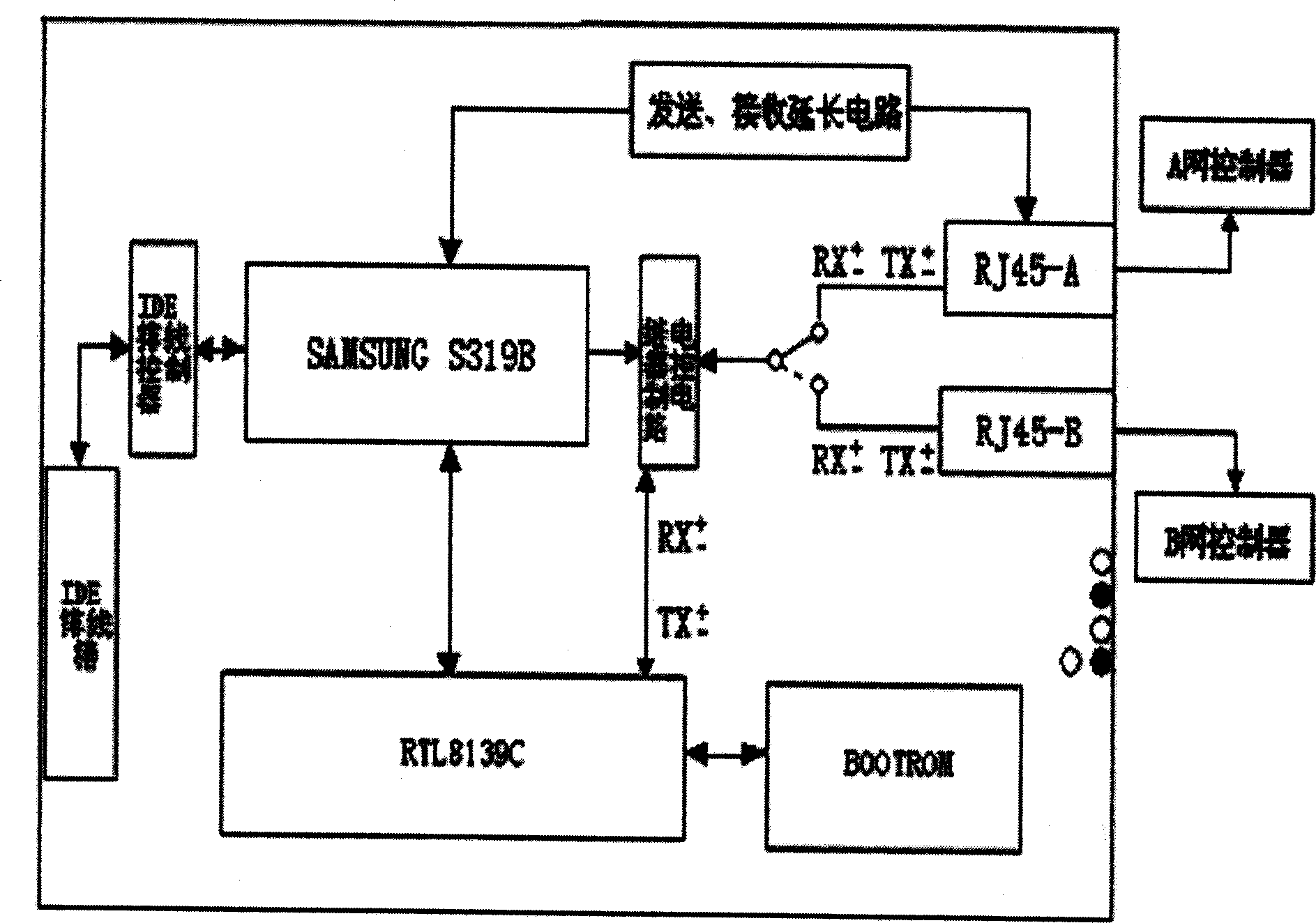
[0020] The present invention will be further described in detail below in conjunction with the accompanying drawings.

[0021] The dual network port physical isolation card of the present invention, such as figure 1 As shown, it includes a network chip, the network chip RTL8139C type network chip, the network chip is respectively interconnected with the microcontroller chip, the network selection chip and the relay control circuit, and the microcontroller chip is a SAMSUNG S319B type of 8-bit ARM chip chip, the network selection chip is a Bootrom type chip, and the microcontroller chip is connected to the IDE interface and the relay control circuit respectively, and one of the relay control circuits is located in two RJ45 twisted pairs leading to different networks respectively. The two RJ45 twisted pairs are respectively connected to the internal network controller and the external network controller, that is, network A and network B in the figure. The dual network port physica


PUM


Abstract

The invention provides a double-netport physical isolation card to use effectively double-network resource and realize true physical isolation, which comprises a network chip interconnected to microcontroller chip that connects to IDE interface and following control circuit, network selection chip and relay control circuit selected set on two RJ45 twisted-pair to different network.

Description


Claims


Application Information

Patent Timeline
Owner CATECH TECH
Why Eureka
Try Eureka