Kinetic energy illuminator
A light-emitting device and kinetic energy technology, which is applied in the field of optoelectronic technology and products, can solve problems such as environmental pollution and limit the service life of products, and achieve the effects of low cost, improved energy conversion efficiency, and convenient power transmission
- Summary
- Abstract
- Description
- Claims
- Application Information
AI Technical Summary
Problems solved by technology
Method used
Image

Examples
Example Embodiment
[0054] Example 1: Kinetic energy luminous shoes
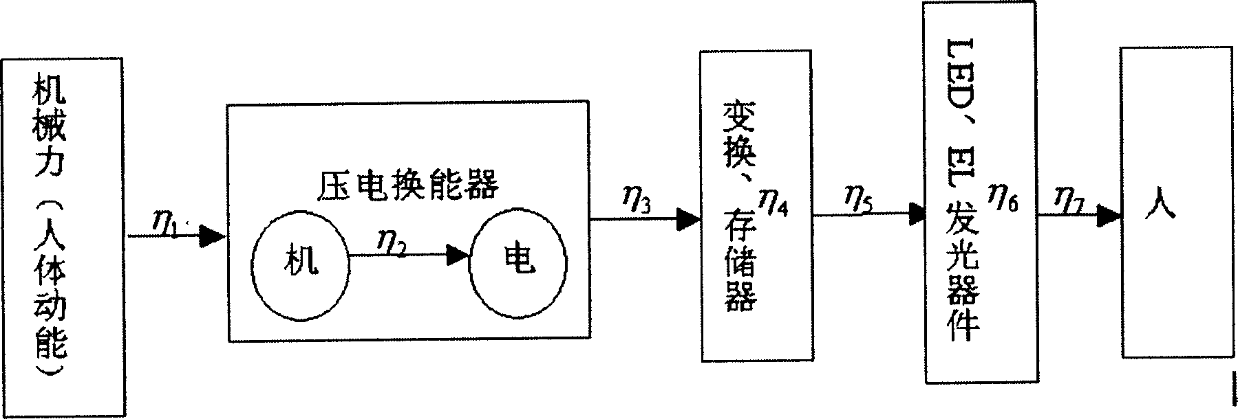
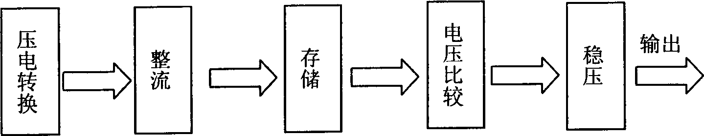
[0055] See Figure 4-7 This embodiment is applied to light-emitting shoes. The PZT piezoelectric power generation transducer 1 is placed on the heel of the shoe to make it work in a forced vibration mode, and two groups of light-emitting diodes 2 connected in antiphase and parallel are connected. When walking, the heel forces the transducer to forcibly vibrate, emit an alternating current with the same frequency as the walking, and alternately light up the light-emitting diode group 2 in antiphase and parallel. See the overall schematic diagram of the device Figure 4 , See the structure of PZT piezoelectric generator transducer Figure 5 with Figure 6 , Which includes a combined elastic shell 11 and a rigid shell 15. The shell is provided with an electrode 12, a PZT ceramic 13, a substrate 14 and a buffer material 16. For the circuit connection, please refer to Figure 7 .
[0056] In this embodiment, three links: conversion, storage
Example Embodiment
[0058] Example 2: Vibrating light-emitting keychain
[0059] See Picture 9 In this embodiment, the piezoelectric generator transformer works in a free impact state. The free impact of the small steel ball 33 in the key fob on the piezoelectric element 31 realizes the conversion of vibration energy and illuminates the LED 32 outside the key fob.
Example Embodiment
[0060] Example 3: Vibrating and luminous bouncing ball
[0061] See Picture 10 In this embodiment, the piezoelectric generator converter works in a free vibration state. The length of the piezoelectric generator 41 is slightly smaller than the diameter of the inner shell, so that it can move freely in the inner shell. Through the free collision and friction between the piezoelectric generator transformer 41 and the inner wall of the transparent rigid plastic inner shell 43, it can vibrate freely, realize the conversion of vibration energy, light up the light-emitting diode 42 installed on the piezoelectric generator transformer 41, and wrap it on the outside. The transparent elastic rubber layer 44 adds a luminous effect to the traditional toy bouncing ball.
PUM
 Abstract
Description
Claims
Application Information
 - R&D Engineer
- R&D Manager
- IP Professional
- Industry Leading Data Capabilities
- Powerful AI technology
- Patent DNA Extraction
Browse by: Latest US Patents, China's latest patents, Technical Efficacy Thesaurus, Application Domain, Technology Topic.
© 2024 PatSnap. All rights reserved.Legal|Privacy policy|Modern Slavery Act Transparency Statement|Sitemap