Connecting structure of refrigerant suction pipe for multi-cylinder rotary compressor

A technology of rotary compressor and connection structure, applied to rotary piston type/oscillating piston type pump components, rotary piston type/oscillating piston type pump combination for elastic fluid, components of pumping device for elastic fluid, etc. Direction, can solve problems such as noise, product without structure, inconvenience, etc., to achieve the effect of reducing volume, simplifying composition, and reducing cost

Inactive Publication Date: 2007-01-10
LG ELECTRONICS (TIANJIN) APPLIANCES CO LTD
View PDF0 Cites 1 Cited by
  • Summary
  • Abstract
  • Description
  • Claims
  • Application Information

AI Technical Summary

Benefits of technology

This patented technology allows for easier installation or reduction on costs compared with traditional designs by removing an expensive liquid container from the system without adding extra weight that could affect its performance. Additionally, this design makes it smaller than previous versions while still maintaining their efficiency.

Problems solved by technology

Technologies related to this patented technical problem addressed in this patents include reducing noise during operation while maintaining efficient performance without increasing weight or cost; simplifying assembly processes and minimizing leakage caused by gaps within components like valve parts; enabling precise control over multiple stages (compressors) in different directions, allowing for greater flexibility and reduced overall dimensions.

Method used


Image

  • Connecting structure of refrigerant suction pipe for multi-cylinder rotary compressor
  • Connecting structure of refrigerant suction pipe for multi-cylinder rotary compressor
  • Connecting structure of refrigerant suction pipe for multi-cylinder rotary compressor

Examples


Embodiment Construction

[0050] In order to further explain the technical means and effects of the present invention to achieve the intended purpose of the invention, the connection structure of the refrigerant suction pipe of the multi-cylinder rotary compressor proposed according to the present invention is described below in conjunction with the accompanying drawings and preferred embodiments. Specific embodiments, structures, features and effects thereof are described in detail below.

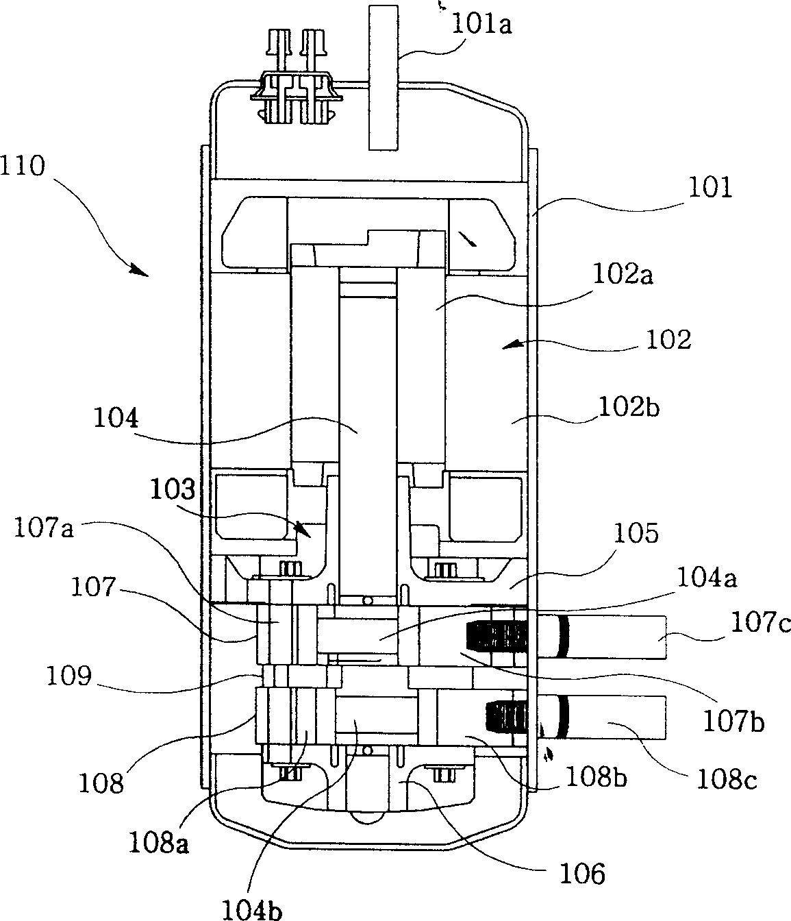
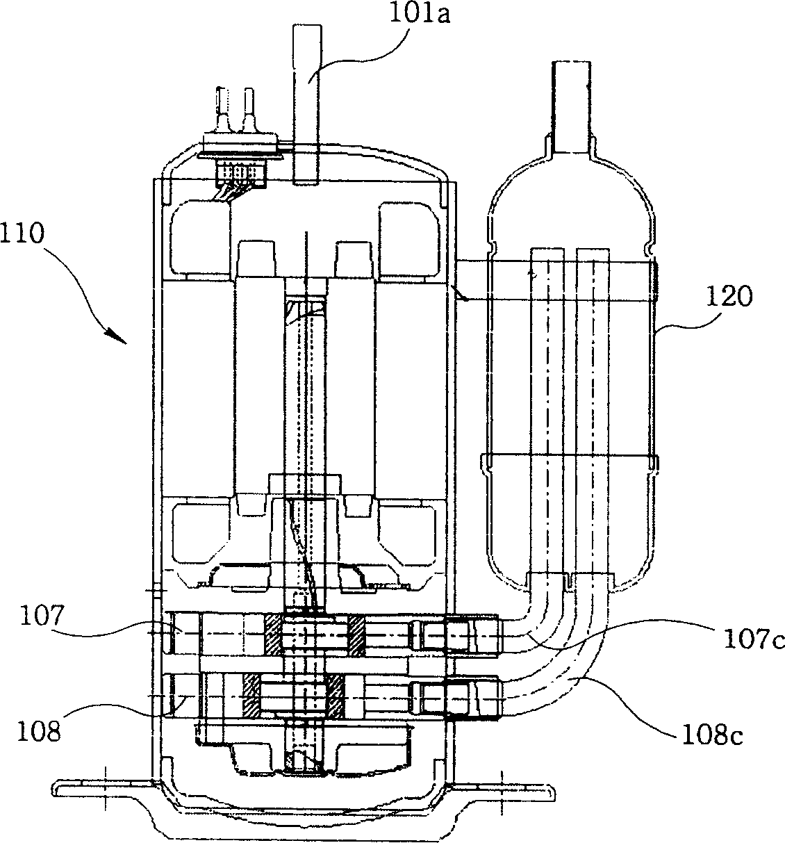
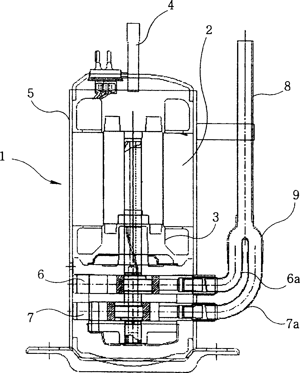
[0051] image 3 is a longitudinal sectional view of the refrigerant suction pipe connection structure of the multi-cylinder rotary compressor according to the present invention, Figure 4 is a longitudinal sectional view according to another embodiment of the present invention, Figure 5 It is a cross-sectional view illustrating a motor connected to a multi-cylinder rotary compressor according to the present invention. The multi-cylinder rotary compressor 1 is composed of the following components; a motor part formin


PUM


Abstract

The invention relates to a connecting structure of refrigerant suction pipe of a multicylinder rotating compressor, comprising: a casing, forming the appearance of the compressor and holding motor and mechanism and formed with refrigerant discharge pipeline; a cylinder part composed of top and bottom refrigerant compressing cylinders and arranged on the mechanism; L-shaped suction pipes, connected with the top and bottom cylinders and make them able to suck refrigerant; and an erect refrigerant inlet pipeline connected with the L-shaped suction pipes and making the circulating refrigerant enter. Omitting the used liquid tank, it can reduce the manufacturing cost of outdoor air-conditioner, able to reduce the bulk of multicylinder rotating compressor, and thus having an efficacy that more compressors can be arranged in a fixed room.

Description


Claims


Application Information

Patent Timeline
Owner LG ELECTRONICS (TIANJIN) APPLIANCES CO LTD
Why Eureka
Try Eureka