Laser-beam mode control device
A mode control, laser beam technology, applied in lasers, laser parts, optics, etc., can solve the problems of large light energy loss, high requirements for optical path adjustment, difficult implementation, etc., to achieve easy adjustment, uncomplicated optical path, and simple structure. Effect
- Summary
- Abstract
- Description
- Claims
- Application Information
AI Technical Summary
Benefits of technology
Problems solved by technology
Method used
Image

Examples
Embodiment 1
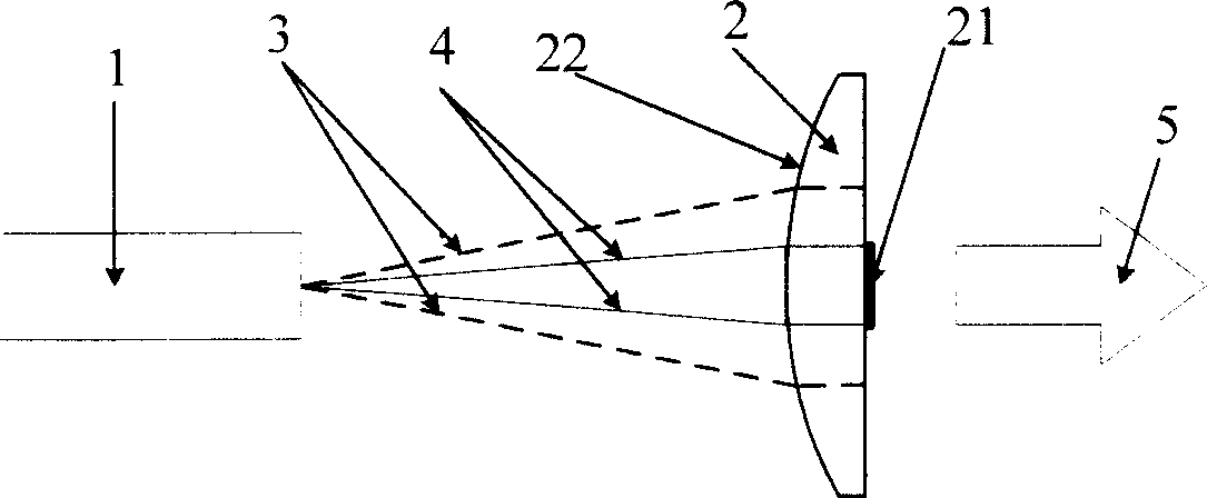
[0015] Nd:YVO to a diode pump source 4 The solid-state laser achieves mode control, and the pump source used is an 810nm diode array laser, Nd:YVO 4 Crystal length 1mm, Nd:YVO 4 One end of the crystal is coated with a 1064nm high-reflection film and a 810nm high-transparency two-color film as the input end of the pump light of the laser 1, and the other end is coated with a 1064nm wavelength laser semi-permeable film 21 as the output end of the laser, with a reflectivity of 15%. The diameter of our used plano-convex lens 2 is 30mm, focal length is 150mm, the convex surface is plated with 1064nm anti-reflection coating, and the small circular surface with a radius of 0.5mm at the plane center of the plano-convex lens is plated with a semi-transparent film 21 with 80% reflectance to 1064nm. It is ensured that only the low-order mode laser beam 4 oscillates in the composite cavity to obtain high-quality laser output 5 . The area of the small circular surface with a certain radiu
Embodiment 2
[0017] To achieve mode control for a fiber laser 1, the pump light source used is a diode array laser with a wavelength of 975nm, the fiber used is a D-shaped inner cladding, the major and minor axes of the inner cladding are 450 μm / 400 μm, and the numerical aperture of the inner cladding is NA=0.37 , the Yb-doped fiber core diameter is 30 μm, the fiber core numerical aperture NA=0.16, and the fiber length is 18.2 m. One end of the fiber is placed with a dichroic film as the pump light input end of the laser. The dichroic film is highly transparent to 975nm and highly reflective to 1080nm. The other end of the fiber is polished and has a Fresnel reflectivity of 4% as the output end of the laser. The diameter of the plano-convex lens 2 we used is 30mm, the focal length is 30mm, the convex surface is coated with a 1080nm anti-reflection coating, and the center of the plane is coated with a semi-transparent coating with a radius of 0.5mm, 1mm and 1.5mm, which has a reflectivity of
PUM
 Abstract
Description
Claims
Application Information
 - R&D Engineer
- R&D Manager
- IP Professional
- Industry Leading Data Capabilities
- Powerful AI technology
- Patent DNA Extraction
Browse by: Latest US Patents, China's latest patents, Technical Efficacy Thesaurus, Application Domain, Technology Topic.
© 2024 PatSnap. All rights reserved.Legal|Privacy policy|Modern Slavery Act Transparency Statement|Sitemap