Electrical connector
- Summary
- Abstract
- Description
- Claims
- Application Information
AI Technical Summary
Benefits of technology
Problems solved by technology
Method used
Image

Examples
first embodiment
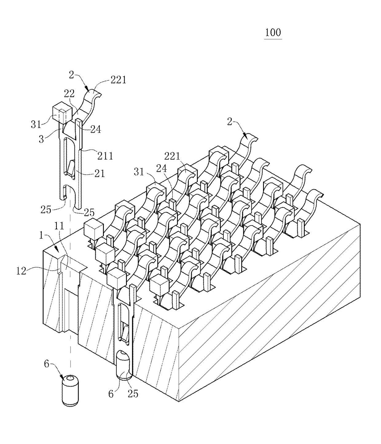
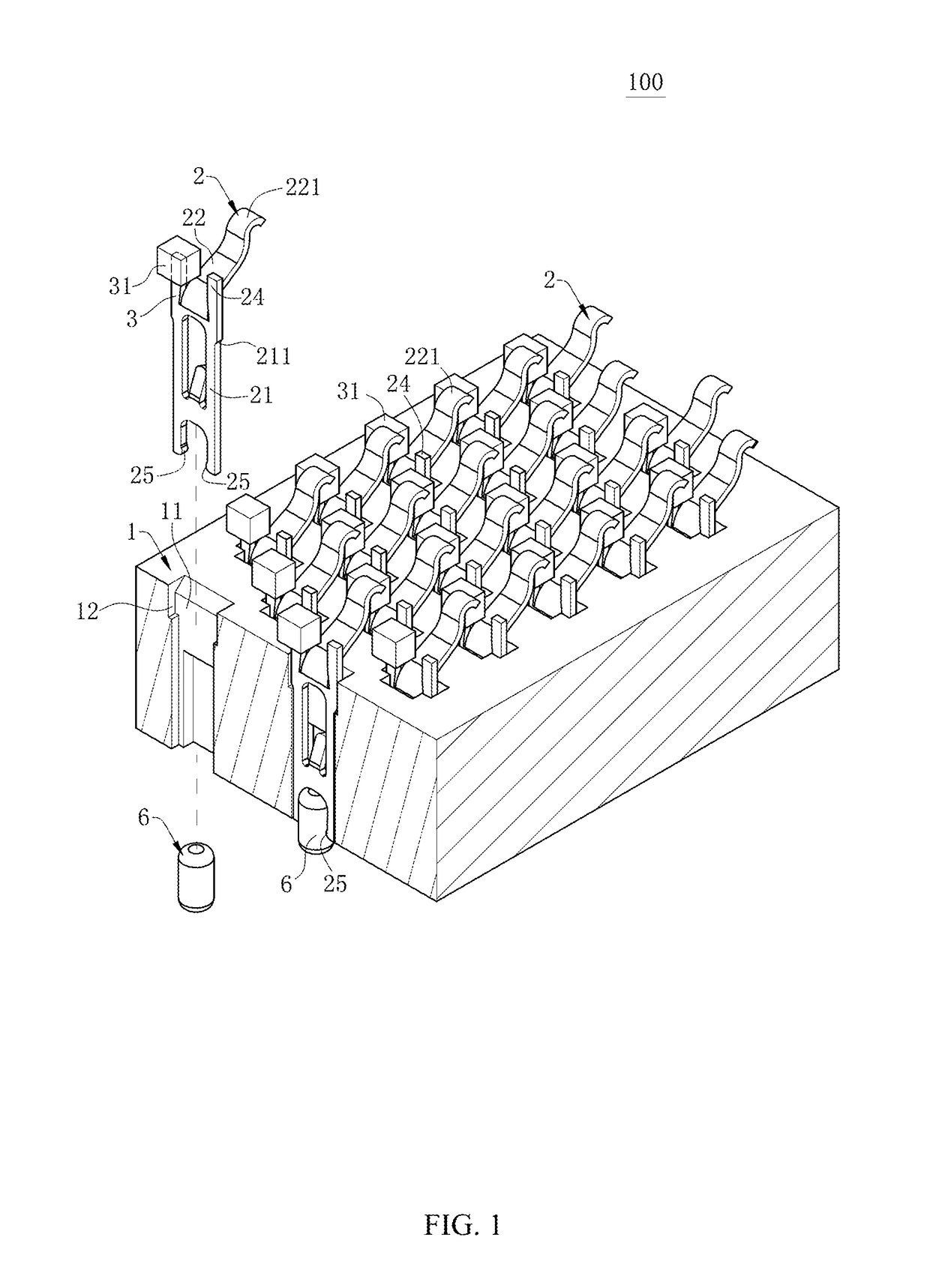
[0048]As shown in FIG. 1 and FIG. 4, an electrical connector 100 according to the present invention is used to electrically connect a chip module 4 to a circuit board 5. The chip module 4 is provided with multiple contact pads 41. The electrical connector 100 includes an insulating body 1, multiple terminals 2 accommodated in the insulating body 1 respectively, and multiple metal connecting portions 3 provided on the insulating body 1 respectively.
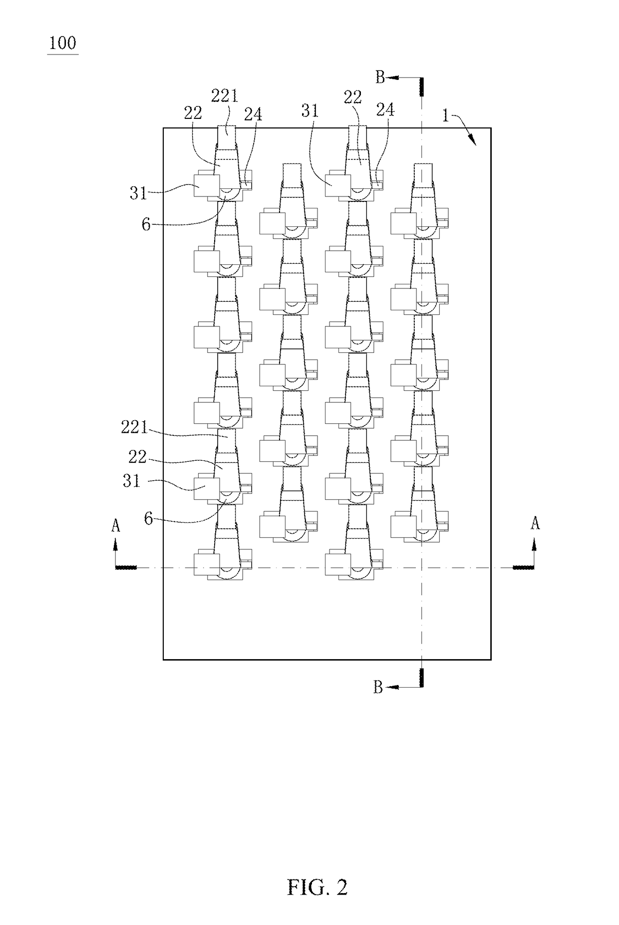
[0049]As shown in FIG. 1 and FIG. 2, multiple accommodating grooves 11 are formed in the insulating body 1 penetratingly downward from top. The accommodating grooves 11 are distributed in the insulating body 1 staggeredly. The accommodating grooves 11 are arranged in multiple columns in a front-rear direction, and arranged in multiple rows in a left-right direction. Each of two sides of each of the accommodating grooves 11 is provided with a fastening slot 12. A plurality of positioning tables (not shown in the drawings, hereinafter inclusive
second embodiment
[0056]FIG. 5 and FIG. 6 show the present invention. The second embodiment is different from the first embodiment in that each of the metal connecting portions 3 and each of the terminals 2 are separately molded, and each of the metal connecting portions 3 is inserted into the insulating body 1 and located at one side of the extending arm 22. One end of each of the metal connecting portions 3 has an insulating supporting portion 31, and the insulating supporting portion 31 is used to abut the chip module 4 and is not in contact with or not electrically connected with any of the contact pads 41.
[0057]Each of the metal connecting portions 3 has two projecting portions 33. A lower surface of each of the projecting portions 33 is fastened on the upper surface of the insulating body 1 to stop the metal connecting portion 3 from moving downward. A strip breaking portion 32 extends vertically upward from the end of the metal connecting portion 3 connected with the insulating supporting portion
third embodiment
[0059]FIG. 7 and FIG. 8 show the present invention. The third embodiment is different from the second embodiment in that the lower surfaces of the insulating supporting portions 31 abut the upper surface of the main body portion 21 to stop the main body portion 21 from moving upward. Meanwhile, the insulating supporting portion 31 is located above the main body portion 21. Compared with the existing electrical connector 100 where the insulating supporting portion 31 and the main body portion 21 are arranged in a staggered mode, the insulating supporting portion 31 of the electrical connector 100 according to the embodiment can fully use the space above the main body portion 21, thus increasing the area of the insulating supporting portion 31, and allowing the insulating supporting portion 31 to support a chip module 4 more stably.
[0060]To sum up, the electrical connector 100 according to certain embodiments of the present invention has the following beneficial effects:
[0061](1) Accordi
PUM
 Abstract
Description
Claims
Application Information
 - R&D Engineer
- R&D Manager
- IP Professional
- Industry Leading Data Capabilities
- Powerful AI technology
- Patent DNA Extraction
Browse by: Latest US Patents, China's latest patents, Technical Efficacy Thesaurus, Application Domain, Technology Topic.
© 2024 PatSnap. All rights reserved.Legal|Privacy policy|Modern Slavery Act Transparency Statement|Sitemap