Wall hanger assembly

Inactive Publication Date: 2004-08-19
SKORKA RICHARD
View PDF11 Cites 30 Cited by
  • Summary
  • Abstract
  • Description
  • Claims
  • Application Information

AI Technical Summary

Problems solved by technology

In the past, prior practice in mounting a picture frame or other article upon a wall with a hook-like member never seriously considered any shearing or downward force that caused an erosion or deterioration of the wallboa

Method used


Image

  • Wall hanger assembly
  • Wall hanger assembly
  • Wall hanger assembly

Examples


Embodiment Construction

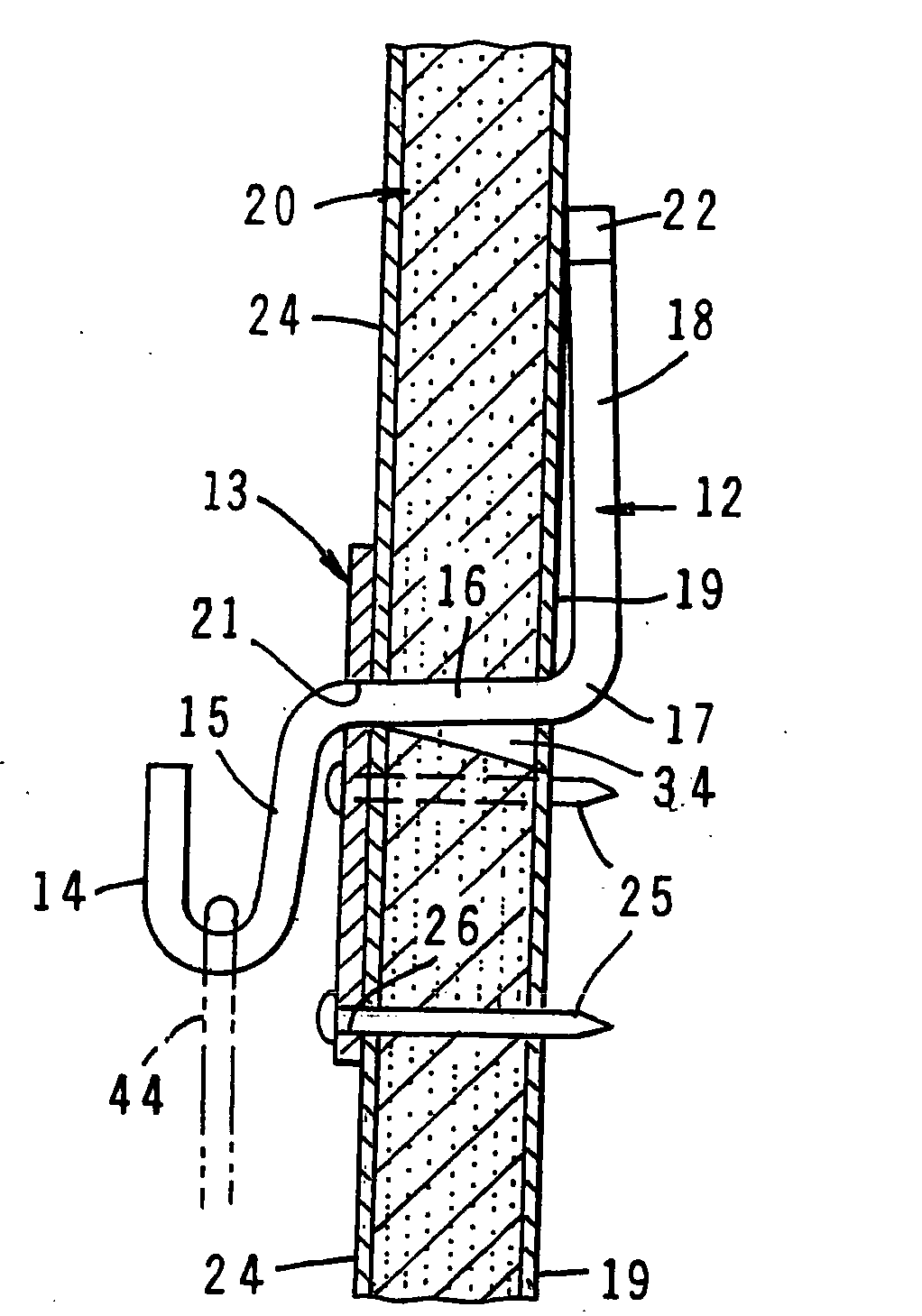
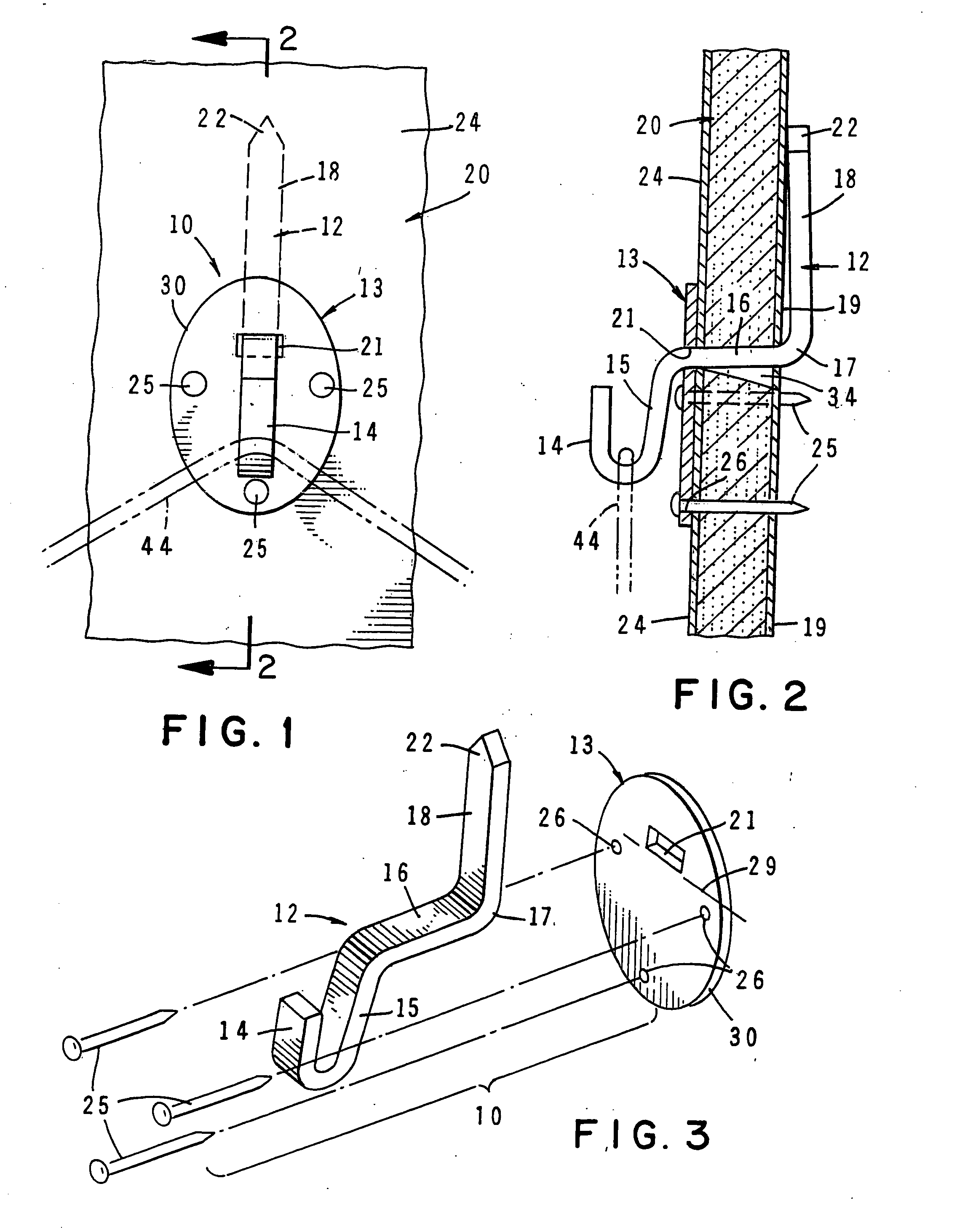
[0028] Referring to the drawings wherein reference characters therein refer to like numeral hereinafter, FIGS. 1, 2, and 3 illustrate the hanger device 10 of this invention. Device 10 is of a combined pair of elements 12, 13, element 12 being of an integral body configuration fabricated into the form of a member or clip that includes a hook 14 mounted on a downwardly turned leg 15 extending from a horizontally oriented extension member 16 which at the other end of extension member 16 an elbow 17 integrally connects extension member 16 to an upwardly turned arm 18 formed, adapted to abut and engage the back or interior side 19 of a wallboard 20 to which hanger device 10 is to be mounted, Element 13 is a support member, vertically oriented relative to extension member 16, through which the horizontally oriented extension member 16 projects by means of a geometrically configured opening 21 formed through and in the body formation of support member 13.

[0029] The entire length of clip 12 is


PUM


Abstract

A hanger device in an assembly of a clip and a support member for installation upon a wallboard. The clip is formed as one piece, having an upturned arm, a downwardly turned leg and a horizontally oriented extension member connecting the two together. A hook is mounted on leg and a pointed end is provided on the terminal end of the arm. An opening is formed in support member so as to mate geometrically to the rectangular cross section of extension member to prevent turning of clip after installation of device in wallboard. A plurality of spaced-apart apertures is provided in the support member for insertion of fasteners to attach support member to the wallboard. The device of the invention carries much more weight than do the present state-of-the art hangers.

Description


Claims


Application Information

Patent Timeline
Owner SKORKA RICHARD
Why Eureka
Try Eureka