Cathode-ray tube
a cathode-ray tube and cathode ray tube technology, applied in cathode ray tubes/electron beam tubes, electric discharge tubes, electrical apparatus, etc., can solve the problems of inability to achieve set bias voltage adjustment, inability to achieve set equality between ik values, and difficulty for users to perform such adjustment. achieve the effect of high-quality imag
- Summary
- Abstract
- Description
- Claims
- Application Information
AI Technical Summary
Benefits of technology
Problems solved by technology
Method used
Image

Examples
first embodiment
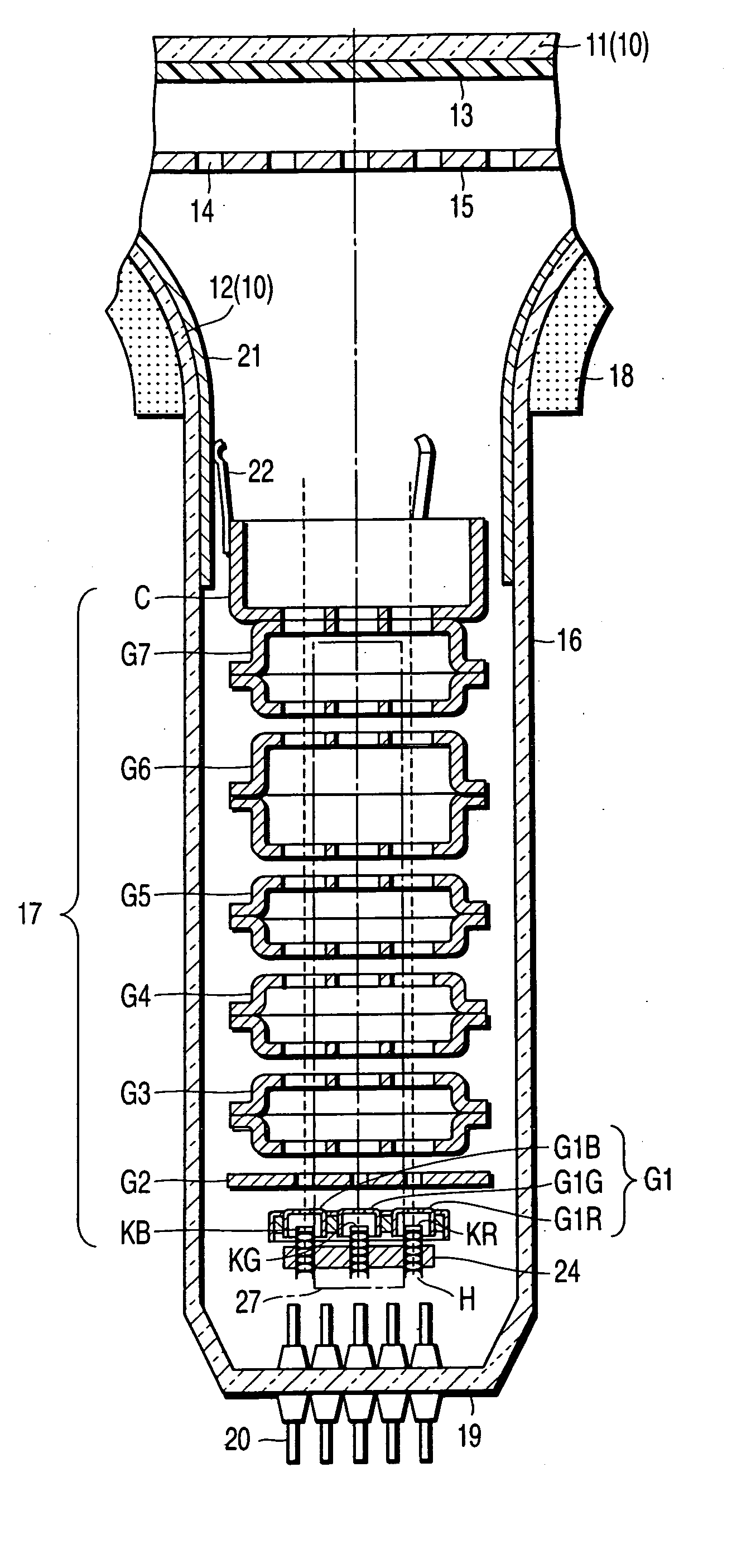
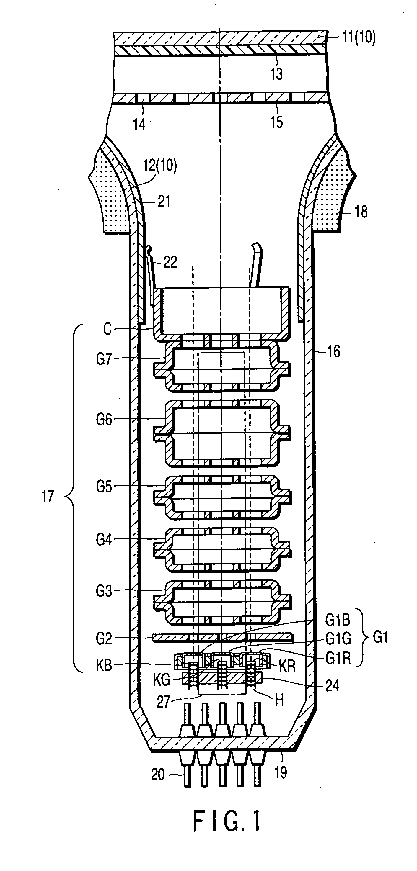
[0051] In the electron gun assembly each of the first grids G1 is formed of a cup-shaped electrode body having an electron beam passage hole. The bottom face of each cup-shaped electrode body has one electron beam passage hole. The second grid G2 is formed of a plate electrode body and has three electron beam passage holes. Each of the third to seventh grids G3 to G7 is formed of a plurality of cup-shaped electrode bodies that are combined. The bottom face of each cup-shaped electrode body has three electron beam passage holes. The cathodes K, heaters H and grids are integrally fixed by a pair of insulating support members 27 that are formed of glass.
[0052] A stem section 19 is provided at an end portion of the neck 16. The stem section 19 seals the envelope 10 in a vacuum state. A plurality of stem pins 20 penetrate the stem section 19 in the state in which the envelope 10 is kept airtight. The stem pins 20 are electrically connected to the respective electrodes of the electron gun a
second embodiment
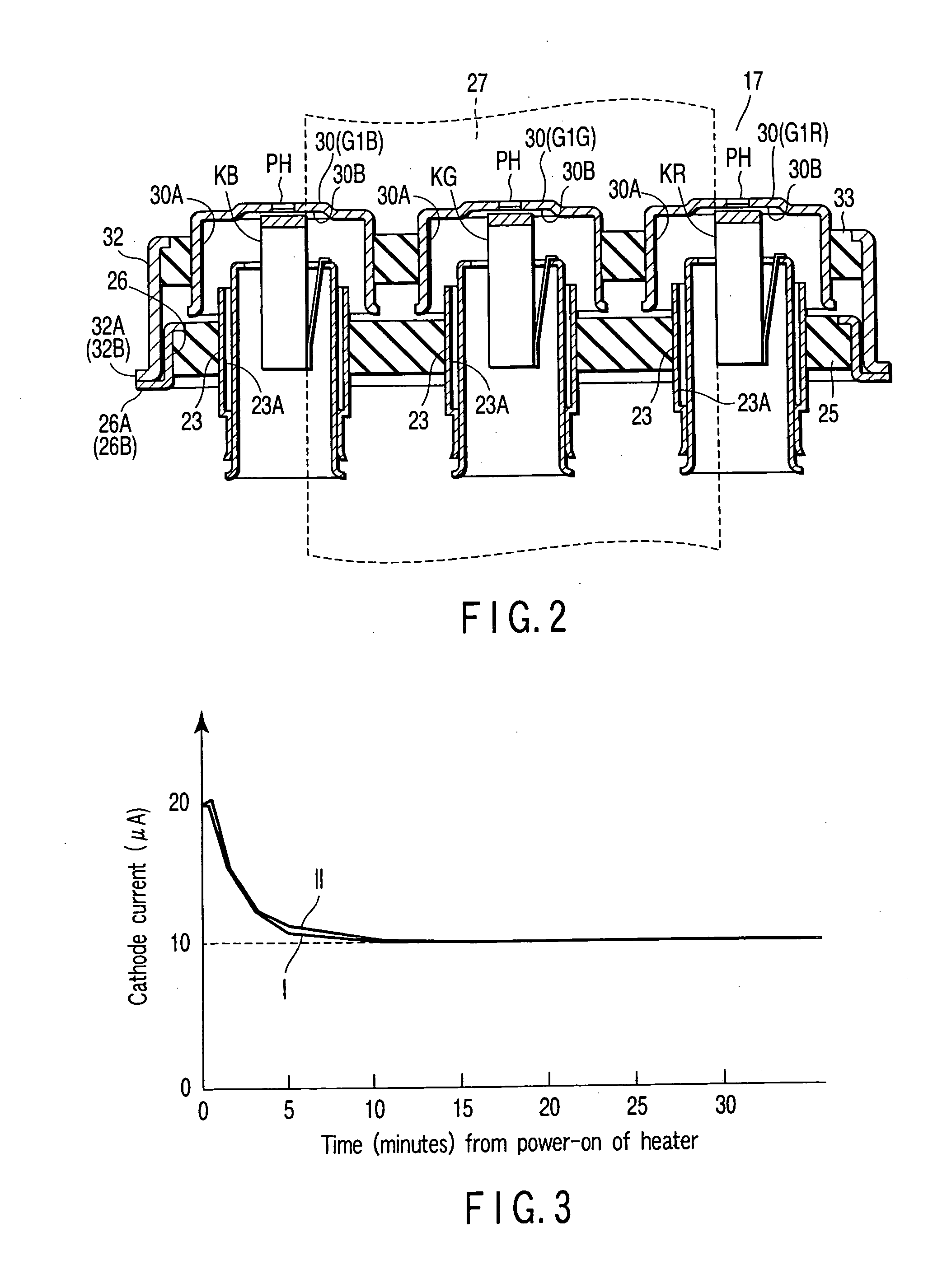
[0081] Furthermore, in the second embodiment, the first grids G1 are constructed as follows. The three first grid support members 41 are made to penetrate the insulation member 33. The cylindrical member 32 is then fixed so as to surround the insulation member 33. Thereafter, the three first grid discs 40 are fixed by welding to the associated three first grid support members 41. It is easy, therefore, to correct non-uniformity in attachment precision, such as the pitch, flatness and linearity of the three first grid support members 41, which will occur when the first grids G1 are fixed. The precision in assembly of the three first grid discs 40 can be enhanced.
[0082] Hence, in the electron gun assembly with the above-described structure, each of the IK values can quickly be set at the predetermined fixed value from the time immediately after power-on. In addition, as regards the color cathode-ray tube that incorporates this electron gun assembly, when the color cathode-ray tube is ass
PUM
 Abstract
Description
Claims
Application Information
 - R&D Engineer
- R&D Manager
- IP Professional
- Industry Leading Data Capabilities
- Powerful AI technology
- Patent DNA Extraction
Browse by: Latest US Patents, China's latest patents, Technical Efficacy Thesaurus, Application Domain, Technology Topic.
© 2024 PatSnap. All rights reserved.Legal|Privacy policy|Modern Slavery Act Transparency Statement|Sitemap