Sampler and method of dispensing and cooling a fluid

a fluid and sampler technology, applied in the field of sampler and to a fluid dispensing and cooling method, can solve the problems of too large activity of the fluid sample until the time of examination, and the time elapse between sampling and the examination of the sample, so as to reduce the activity of the fluid sample very quickly

Inactive Publication Date: 2005-01-27
EHNDRESS KHAUZER GMBKH KO KG
View PDF12 Cites 13 Cited by
  • Summary
  • Abstract
  • Description
  • Claims
  • Application Information

AI Technical Summary

Benefits of technology

The technical effect of this inventive technology is reducing the amount of liquid drawn from an organism's blood when they are being analyzed for medical purposes while still maintaining their quality level. By doing so, these methods allow researchers more efficient ways to analyze samples without losing valuable material.

Problems solved by technology

This patents describes various technical problem addressed in these documents relating to controlling the amount of certain materials present (substance) within liquid samples collected through aspirators. These liquids can vary widely depending upon factors like ambient conditions and changes in concentration levels due to biology reactions taking place inside them. Existing methods involve measuring the active material content separately beforehand, followed by adjustment based solely on its effectiveness under specific environmental variables. However, it takes several hours to measure each component's level accurately enough to ensure accurate results even if there were no significant difference in the original state after measurement.

Method used


Image

  • Sampler and method of dispensing and cooling a fluid
  • Sampler and method of dispensing and cooling a fluid
  • Sampler and method of dispensing and cooling a fluid

Examples


first embodiment

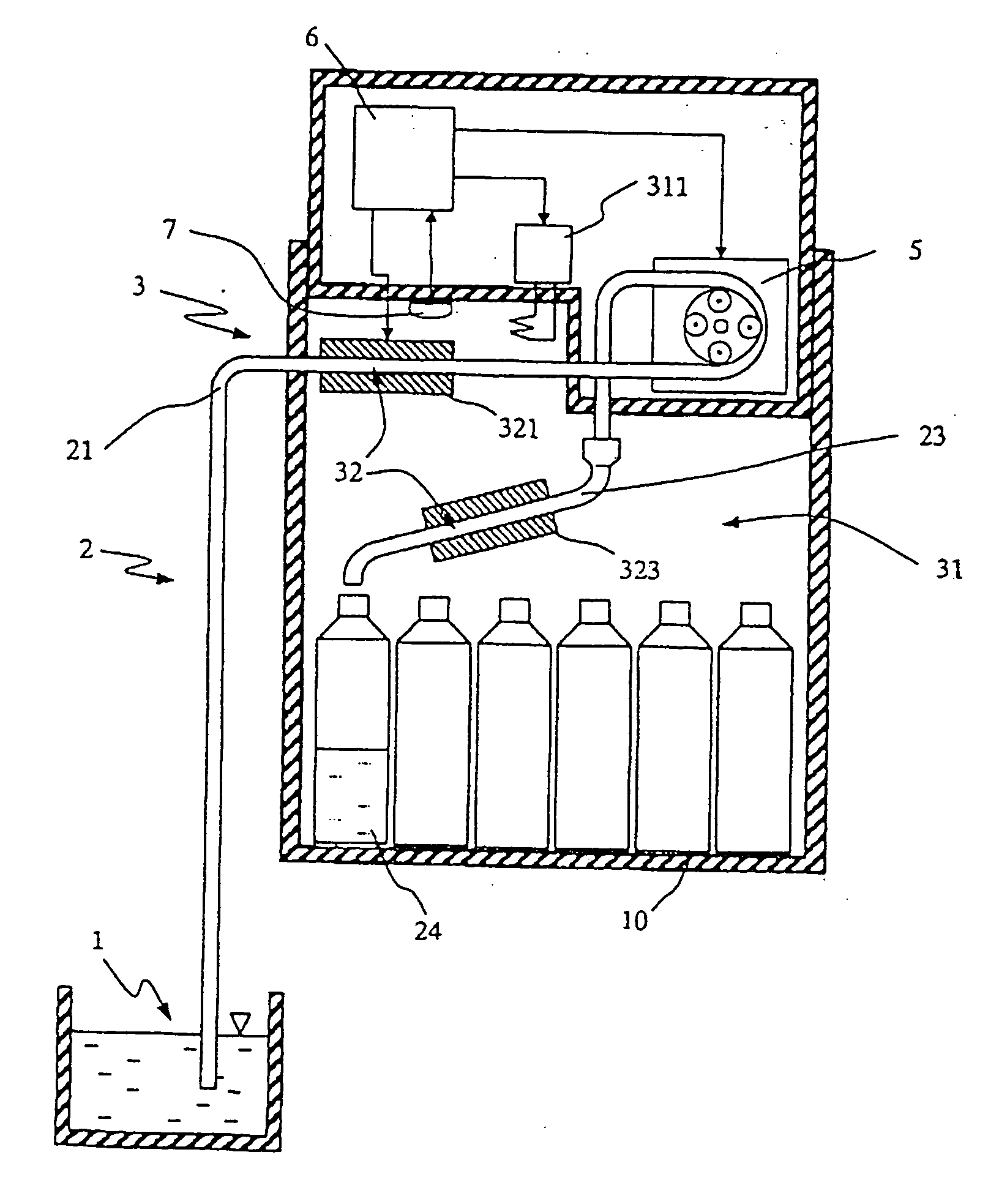
FIG. 1 schematically shows a sampler;

second embodiment

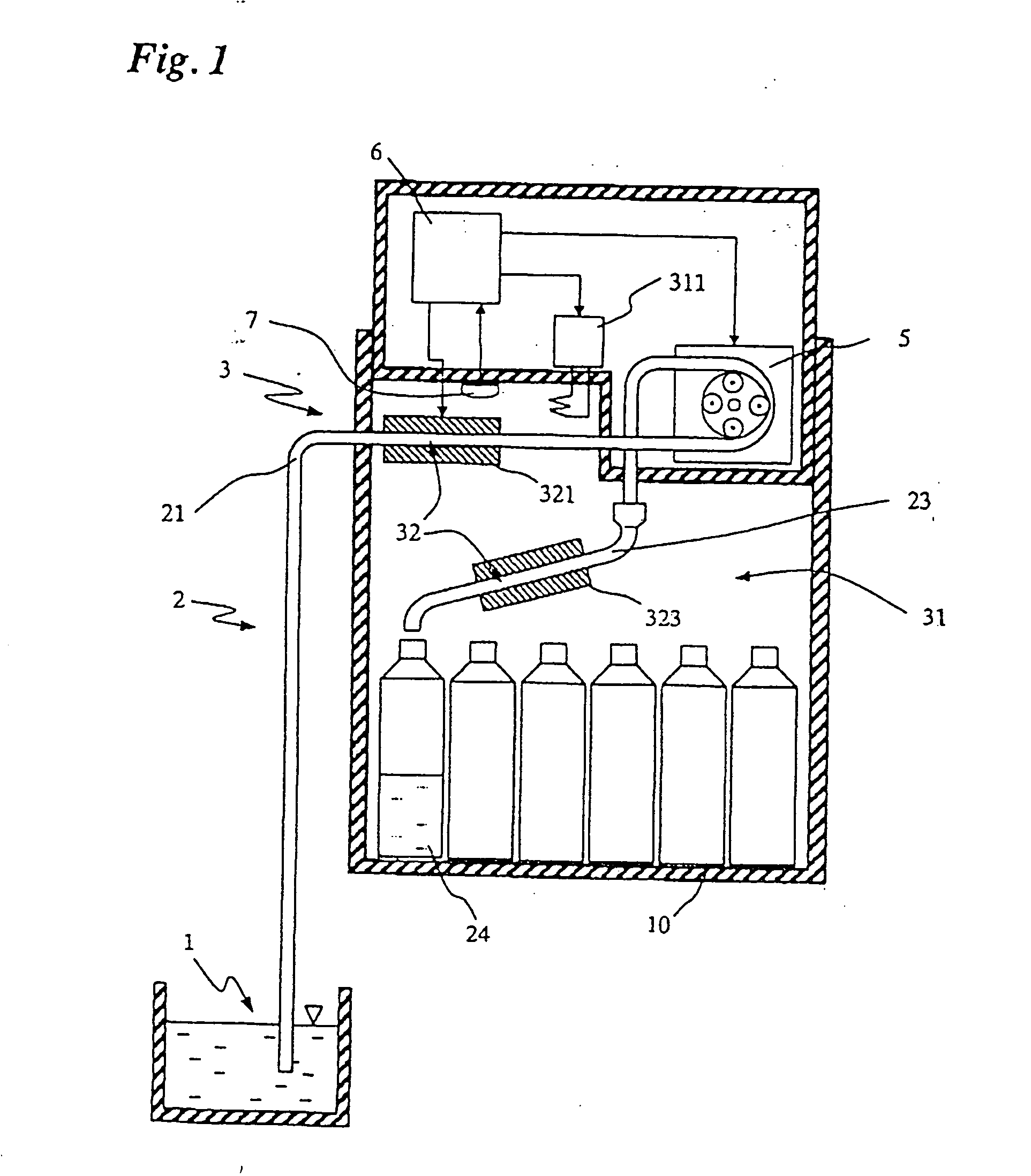
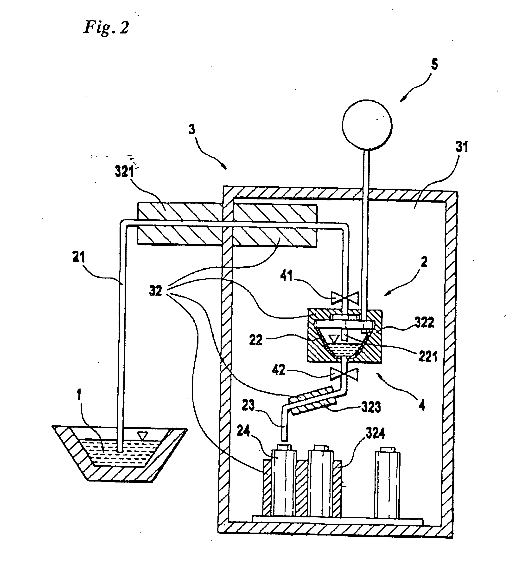
FIG. 2 schematically shows a sampler; and

FIG. 3 shows temperature-time characteristics in the sampler of FIG. 1 or 2, which are set using the method of the invention.

FIGS. 1 and 2 each show schematically a sampler for withdrawing a fluid, particularly an aqueous fluid, at a sampling location 1 and for metering, dispensing, and storing a sample of the fluid. The sampler comprises a vessel assembly 2 of a predeterminable volume which serves to conduct the withdrawn fluid and hold the fluid sample, and which is disposed, at least in part, in a cabinet 10, particularly in a single cabinet.

The sampler may be both a stationary sampler and a transportable sampler.

Vessel assembly 2 comprises at least one intake vessel 21 for withdrawing and conducting the fluid and, at least during operation, a storage vessel 24 for storing the fluid sample.

Intake vessel 21 is tubular in shape and has an inlet-side first end and an outlet-side second end. Preferably, intake vessel 21 is implemented, at l


PUM


Abstract

The sampler comprises a vessel assembly for taking, conducting, and storing a fluid sample to be stored at a predeterminable storage temperature as well as a cooling assembly, thermally coupled to the vessel assembly, for cooling the fluid sample. The cooling assembly has a first cooling volume, which encompasses the vessel assembly, and a second cooling volume, which jackets the vessel assembly. To cool the fluid sample, the internal temperature of the vessel assembly is lowered by means of the cooling assembly prior to and/or during the dispensing of the fluid sample, and the fluid is subsequently conducted or held in the vessel assembly.

Description


Claims


Application Information

Patent Timeline
Owner EHNDRESS KHAUZER GMBKH KO KG
Why Eureka
Try Eureka