Latching mechanism for combustion chamber plate of a fastener driving tool

a technology of gas fastener and ignition mechanism, which is applied in the direction of nailing tools, hot gas positive displacement engine plants, combustion engines, etc., can solve the problems of increasing the risk of costly repairs, affecting the efficiency of the tool, and the multitude of components, so as to achieve the effect of less manufacturing and repair costs, and rapid combustion of fuel air mixtur

Inactive Publication Date: 2005-05-05
ILLINOIS TOOL WORKS INC
View PDF19 Cites 17 Cited by
  • Summary
  • Abstract
  • Description
  • Claims
  • Application Information

AI Technical Summary

Benefits of technology

This patented design includes an improved combustor system with a moveable panel or lever used instead of traditional electrical components such as switches. It allows for precise control over how much gas (fuel) should mix together before igniting it inside the engine cylinder. Additionally, there's no moving parts like springs that could increase pressure on certain areas during operation due to temperature differences across different locations within the device. These technical improvements make this technology more efficient and reliable compared to current designs.

Problems solved by technology

Technologies related to improving an improved design for a compact combustive power tool called a combination tool has been developed over time. These improvements aim to simplify assembly processes while maintaining their efficiency during operation. However, existing methods can be complicated because some techniques like injector systems may result in incomplete combusted gases leading to poor performance. Therefore, new designs involving fewer components without increasing complexity must overcome issues associated with previous designs.

Method used


Image

  • Latching mechanism for combustion chamber plate of a fastener driving tool
  • Latching mechanism for combustion chamber plate of a fastener driving tool
  • Latching mechanism for combustion chamber plate of a fastener driving tool

Examples


embodiment 100

[0050] Referring now to FIG. 6, the embodiment 100 is depicted when the latch member 116 is released, or is moved laterally generally outward, after the trigger 79 is fully depressed, causing ignition. A second spring 132 is attached to the sleeve 108 and drives the divider plate 114 downward until a stop 134 disposed on an inner wall 135 of the sleeve 108 engages the divider plate. A first flow volume 136 and a second flow volume 138 are defined in the sleeve volume 126 by the downward displacement of the divider plate 114. The fuel-air mixture flows through holes 140 in the divider plate 114 from the second flow volume 138 to the first flow volume 136. Turbulence is thus created in the first flow volume 136 which is used to produce a faster flame speed.

[0051] Referring now to FIG. 7, combustion occurs in the first flow volume 136 by igniting the fuel air mixture when the divider plate 114 reaches the stop 134. In the preferred embodiment, ignition occurs via a spark plug as is shown

embodiment 150

[0052] Referring now to FIGS. 8-11, another alternative combustion chamber assembly incorporating a latching mechanism is generally designated 150. Components which are shared with the latching mechanism 100 have been designated with identical reference numbers. A distinctive feature of the embodiment 150 is that the latching mechanism uses at least one spring biased latch member and a cam to engage at least one of the latch members. Another feature of the mechanism is that it increases the flow of air and fuel through openings in the divider plate 114, which maximizes the firing response time of the tool. The latching mechanisms of the combustion chamber assembly 10, 100 use a hole size in the divider plate, 44, 114 that optimizes the drive force of the piston. In some applications, the optimal hole size may be too small to allow the divider plate to snap back into the upward position after the tool has been triggered. This affects the rate at which the tool can be repeatedly fired. I


PUM


Abstract

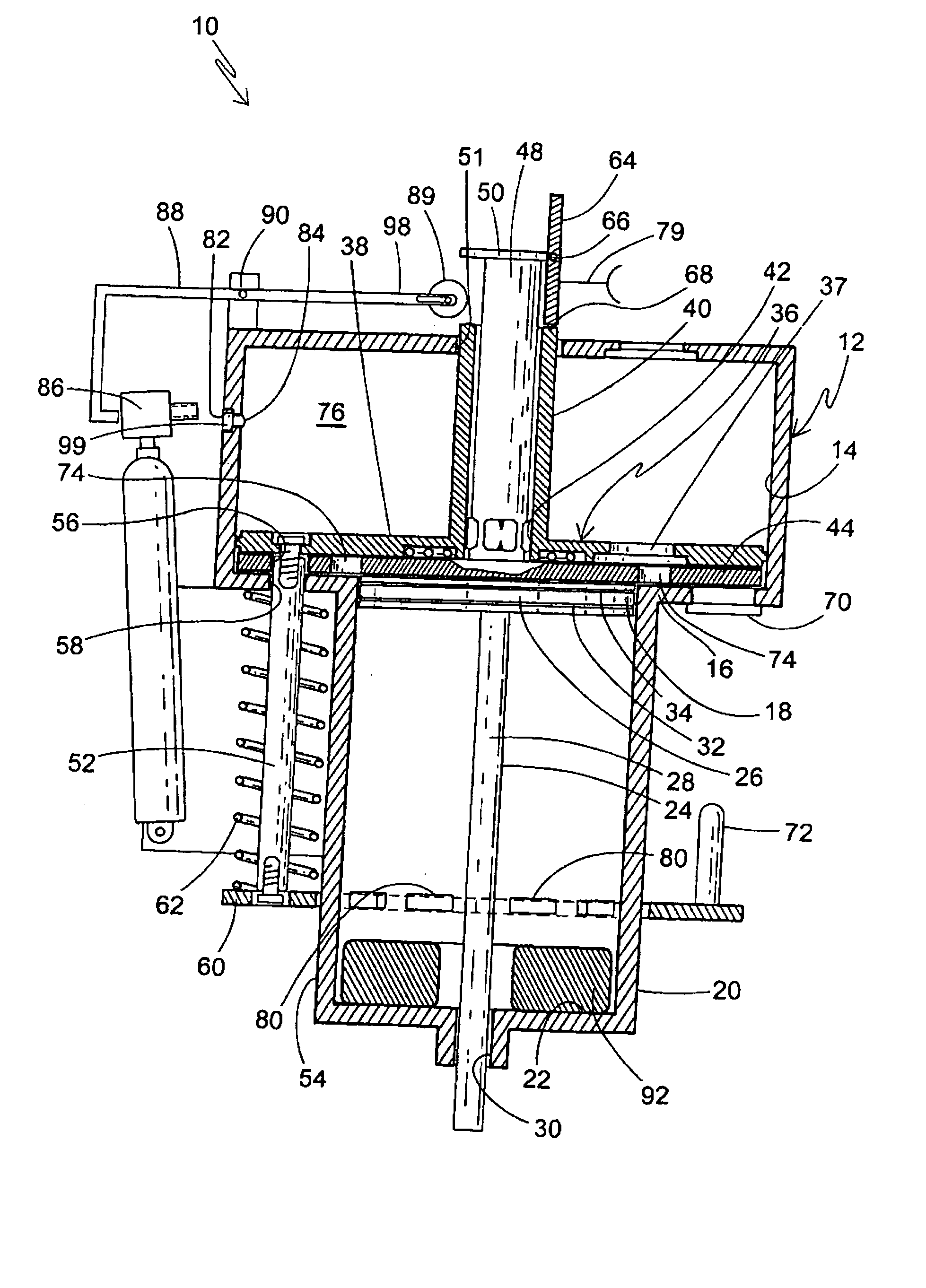
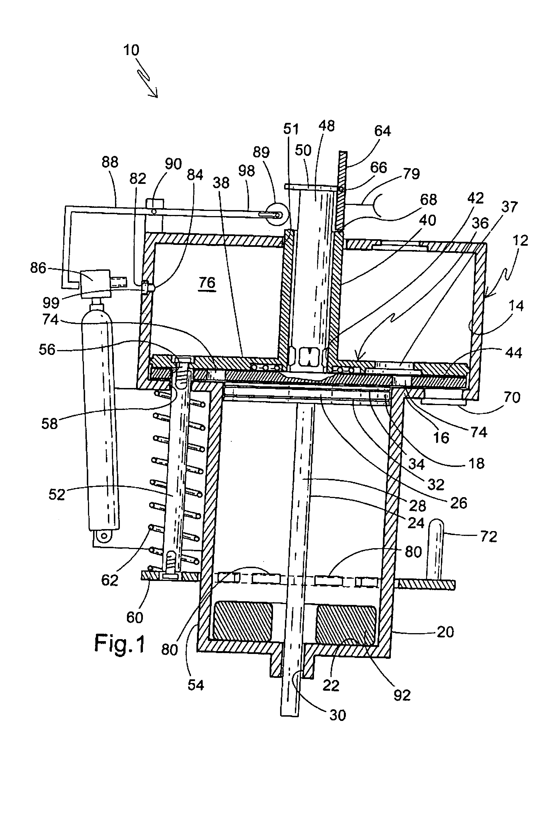
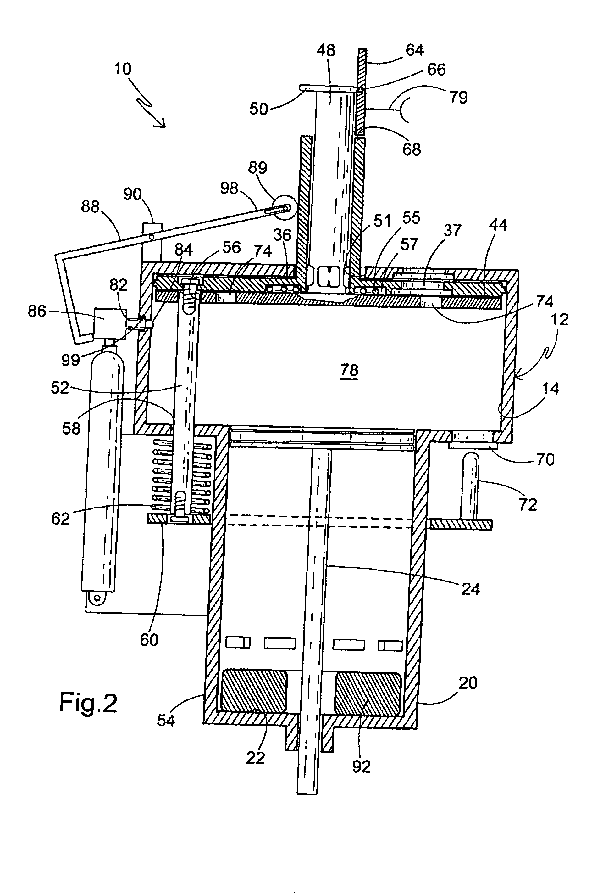
A combustion chamber assembly for use in a combustion tool including a combustion chamber, at least one combustion chamber plate disposed in the chamber, the at least one combustion chamber plate and the chamber members being configured for relative reciprocal movement, the combustion chamber assembly having at least one latch member associated with control of movement of at least one plate within the combustion chamber to divide the chamber into multiple volumes. The combustion chamber assembly further has a release for the latch member for permitting relative movement of the at least one combustion chamber plate and the combustion chamber.

Description


Claims


Application Information

Patent Timeline
Owner ILLINOIS TOOL WORKS INC
Why Eureka
Try Eureka